содержание .. 820 821 822 823 ..
Toyota Sequoia (2005). Manual - part 822
R11656
SST
Wire
Cylinder End
Stopper
F06757
SST
F06758
Vinyl Tape
F08339
Oil Seal
SST
SR–50
–
STEERING
POWER STEERING GEAR
3277
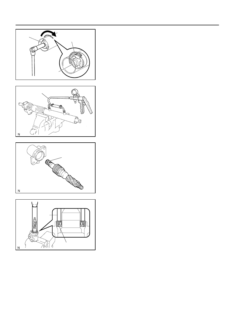
5.
INSTALL CYLINDER END STOPPER
(a)
Align the installation hole for the wire of the stopper with
the slot of the rack housing.
(b)
Install a new wire into the stopper.
(c)
Using SST, turn the stopper clockwise
400°
to 500
°
.
SST
09631–16010
6.
AIR TIGHTNESS TEST
(a)
Install SST to the rack housing.
SST
09631–12071
(b)
Apply 53 kPa (400 mmHg, 15.75 in.Hg) of vacuum for
about 30 seconds.
(c)
Check that there is no change in the vacuum.
If there is change in the vacuum, check the installation of the oil
seals.
7.
INSTALL CONTROL VALVE ASSEMBLY
(a)
To prevent oil seal lip damage, wind vinyl tape on the ser-
rated part of the valve shaft.
(b)
Coat the teflon rings with power steering fluid.
(c)
Install the valve assembly into the valve housing.
NOTICE:
Be careful not to damage the teflon rings and oil seal.
8.
INSTALL OIL SEAL
(a)
Coat a new oil seal lip with power steering fluid.
(b)
Using SST, press in the oil seal.
SST
09612–22011
NOTICE:
Make sure to install the oil seal in the correct direction.
9.
INSTALL CONTROL VALVE HOUSING WITH CON-
TROL VALVE ASSEMBLY
(a)
Place a new gasket on the rack housing.
(b)
Align the matchmarks on the control valve housing with
the one on the rack housing.
(c)
Install the 2 bolts.
Torque: 18 N·m (185 kgf·cm, 13 ft·lbf)