содержание .. 743 744 745 746 ..
Toyota Sequoia (2005). Manual - part 745
TR0DJ–01
F19283
F19751
SST
Groove
F19281
F19293
F19294
–
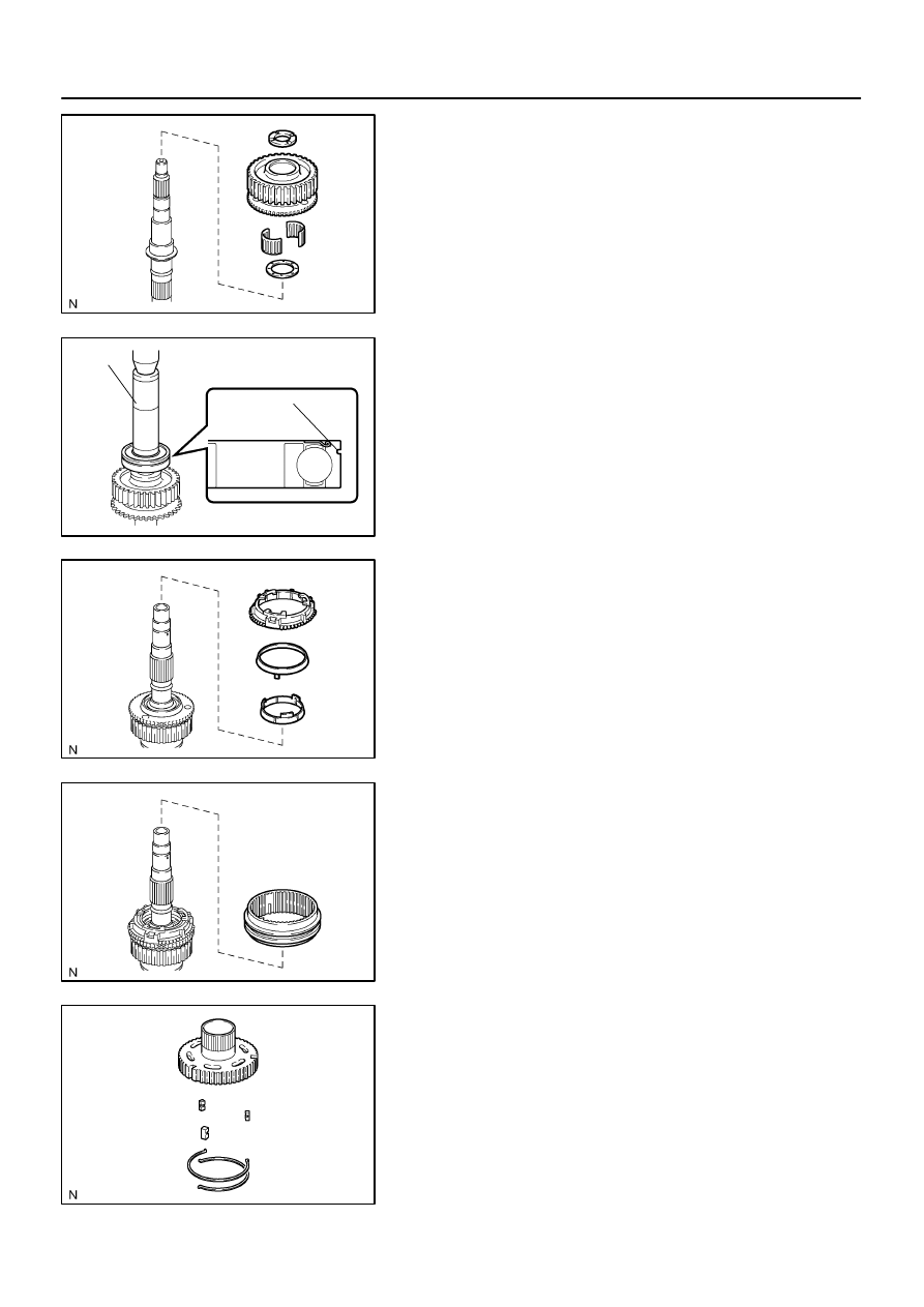
TRANSFER
REAR OUTPUT SHAFT
TR–31
2969
REASSEMBLY
1.
INSTALL DRIVE SPROCKET
(a)
Install the output shaft plate washer and drive sprocket
bearing to the output shaft rear.
(b)
Install the drive sprocket and output shaft spacer No. 1 to
the output shaft rear.
(c)
Using SST and a press, install a new output shaft rear ra-
dial ball bearing.
SST
09316–60011 (09316–00011, 09316–00071)
NOTICE:
Install the output shaft rear radial ball bearing so that the
groove for the snap ring does not face the drive sprocket.
2.
INSTALL SYNCHRONIZER RING SET
3.
INSTALL FRONT DRIVE CLUTCH SLEEVE
4.
INSTALL CLUTCH HUB
(a)
Install the 3 shifting keys to the clutch hub.
(b)
Install the 2 shifting key springs to the clutch hub.
NOTICE:
Position the shifting key springs so that their end gaps are
not aligned.