содержание .. 676 677 678 679 ..
Toyota Sequoia (2005). Manual - part 678
A05095
1
2
4
8
6
3
5
9
7
10
A05094
Front
Painted
Mark
90
°
90
°
A23371
Front Mark
(1 Cavity)
Front
LH
Piston
RH
Piston
Front
Front Mark
(2 Cavities)
EM–122
–
ENGINE MECHANICAL
CYLINDER BLOCK
2701
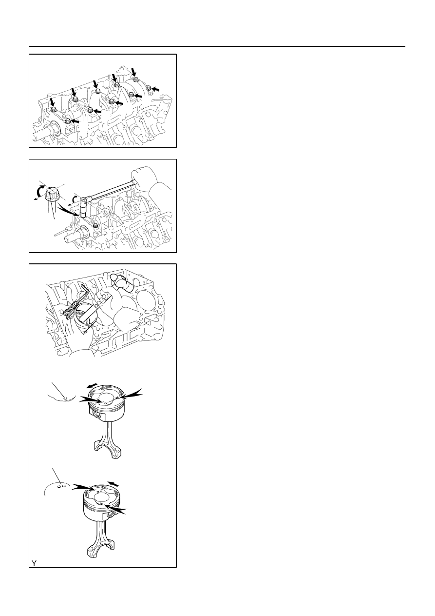
(a)
Apply a light coat of engine oil to the threads and under
the main bearing cap bolts.
(b)
Install and uniformly tighten the 10 main bearing cap bolts
in several steps, in the sequence shown.
Torque: 27 N·m (275 kgf·cm, 20 ft·lbf)
If any of the main bearing cap bolts does not meet the torque
specification, replace the main bearing cap bolt.
(c)
Mark the front of the main bearing cap bolt with paint.
(d)
Retighten the main bearing cap bolts by 90
°
in the numer-
ical order shown.
(e)
Check that the painted mark is now at a 90
°
angle to the
front.
(f)
Check that the crankshaft turns smoothly.
9.
CHECK CRANKSHAFT THRUST CLEARANCE
(See page
)
10.
INSTALL PISTON AND CONNECTING ROD AS-
SEMBLIES
Using a piston ring compressor, push correctly the numbered
piston and connecting rod assemblies into each cylinder with
the front mark of the piston facing forward.
NOTICE:
The shape of the piston differs for the LH and RH banks.
The LH piston is marked with 1 cavity and ”2”, the RH pis-
ton with 2 cavities and ”2”.