Toyota Sequoia (2005). Manual - part 641


  Главная      Automobile - Toyota     Toyota Sequoia - Repair manual 2005 year


поиск по сайту           правообладателям


содержание   ..  639  640  641  642   ..


Toyota Sequoia (2005). Manual - part 641


DIAGNOSTICS

AIR CONDITIONING SYSTEM

DI–2359

2553

INSPECTION PROCEDURE

1

Actuator check.

PREPARATION:
(a)

Remove the glove compartment door to see and check the air inlet damper operation.

(b)

Set to the actuator check mode (See page 

DI–2303

).

(c)

Press the DEF switch and change it to step operation.

CHECK:
Press the DEF switch and check the operation of the air inlet damper.
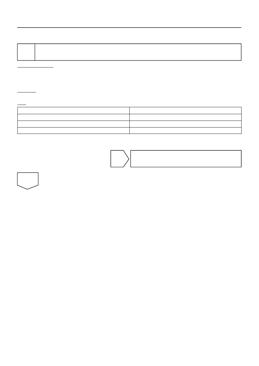
OK:

Display Code

Air Inlet Damper

0 – 2

FRS

3

REC/FRS

4 – 9

REC

HINT:
However, if DTC 42 is displayed, replace the integration control and panel.

OK

Proceed to next circuit inspection shown in
problem symptoms table (See page 

DI–2304

).

NG

I25201

REC

FRS

DI–2360

DIAGNOSTICS

AIR CONDITIONING SYSTEM

2554

2

Check air inlet damper control servomotor.

PREPARATION:
Remove the air inlet servomotor (See page 

AC–49

).

CHECK:
Connect the positive (+) lead to terminal 4 and the negative (–)
lead to terminal 5.
OK:

The lever moves smoothly to the REC position.

CHECK:
Connect the positive (+) lead to terminal 5 and the negative (–)
lead to terminal 4.
OK:

The lever moves smoothly to the FRS position.

NG

Replace air inlet servomotor.

OK

3

Check harness and connector between air inlet servomotor and integration con-
trol and panel (See page 

IN–35

).

NG

Repair or replace harness or connector.

OK

Replace integration control and panel.

I28841

Integration Control
and Panel

5

IJ3

I21

9

RrAMC

RrAMH

L–B

BH1

3

4

R–G

R–G

A34
A/C Water Valve (Rear)

R–G

L–B

2

8

10

L–B

w/ Rear A/C:

7

M.COOL

M.HOT

I21

IJ3

BH1

DIAGNOSTICS

AIR CONDITIONING SYSTEM

DI–2361

2555

DTC

47

Water Valve Damper Control Servomotor
Circuit

CIRCUIT DESCRIPTION

The water valve damper control servomotor is controlled by the integration control and panel and moves the
water valve damper to the desired position.

DTC No.

Detection Item

Trouble Area

47

Water valve damper position sensor value does not change

even if integration control and panel operates water valve

damper control servomotor.


Water valve damper control servomotor


Water valve damper position sensor


Harness or connector between water valve damper control

servomotor and integration control and panel


Harness or connector between water valve damper position

sensor and integration control and panel


Integration control and panel

WIRING DIAGRAM

DI936–04

I28853

5

4

WARM

I28854

COOL

5

4

DI–2362

DIAGNOSTICS

AIR CONDITIONING SYSTEM

2556

INSPECTION PROCEDURE

1

Check water valve damper control servomotor.

PREPARATION:
Remove the water valve servomotor (See page 

AC–42

).

CHECK:
Connect the positive (+) lead to terminal 5 and the negative (–)
lead to terminal 4.
OK:

The lever turns smoothly to the warm side.

CHECK:
Connect the positive (+) lead to terminal 4 and the negative (–)
lead to terminal 5.
OK:

The lever turns smoothly to the cool side.

NG

Replace water valve servomotor.

OK

2

Check harness and connector between water valve servomotor and integration
control and panel (See page 

IN–35

).

NG

Repair or replace harness or connector.

OK

Replace integration control and panel.


содержание   ..  639  640  641  642   ..