Toyota Sequoia (2005). Manual - part 639


  Главная      Automobile - Toyota     Toyota Sequoia - Repair manual 2005 year


поиск по сайту           правообладателям


содержание   ..  637  638  639  640   ..


Toyota Sequoia (2005). Manual - part 639


I25201

REC

FRS

DIAGNOSTICS

AIR CONDITIONING SYSTEM

DI–2351

2545

2

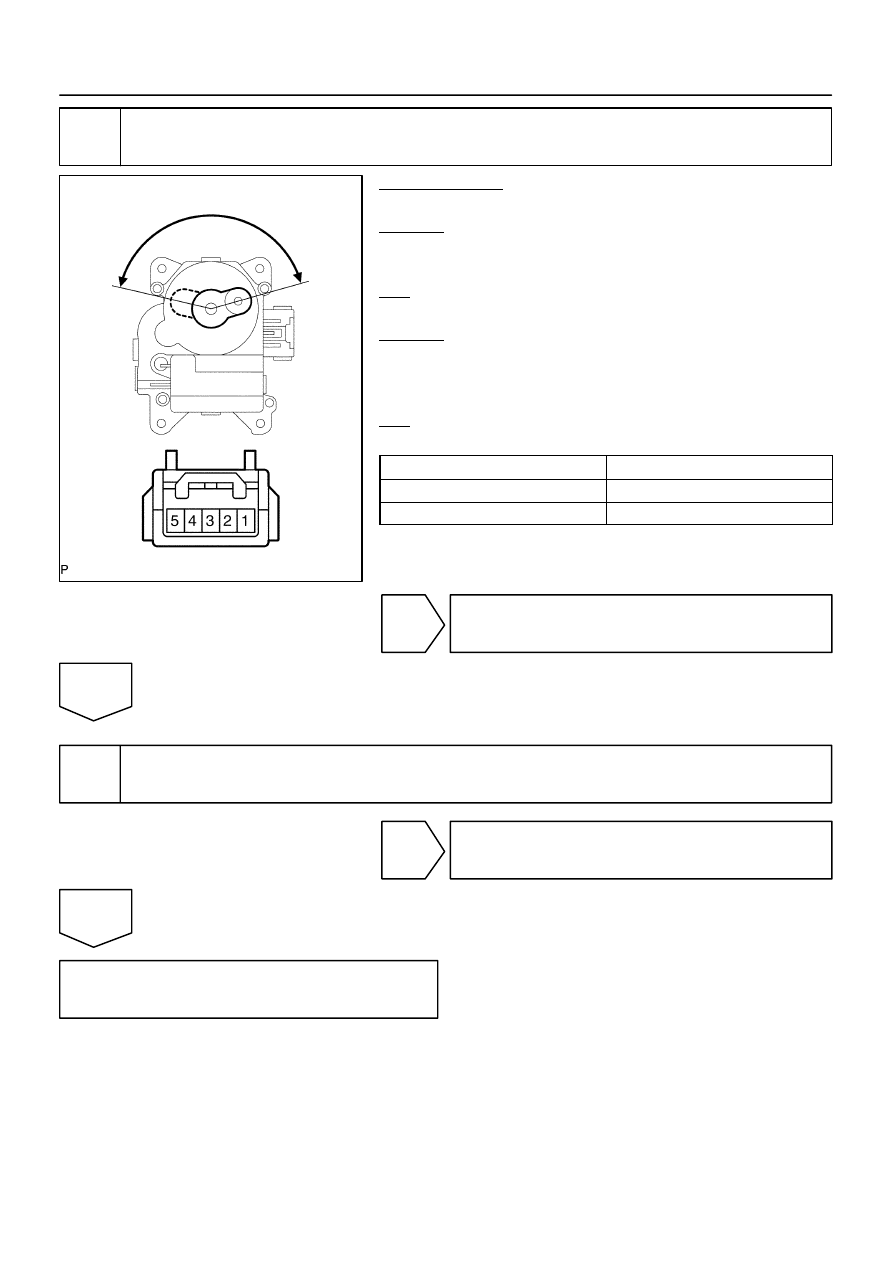
Check air inlet damper position sensor.

PREPARATION:
Remove the air inlet servomotor (See page 

AC–49

).

CHECK:
Measure the resistance between terminals 3 and 2 of the air in-
let servomotor connector.
OK:

Resistance : 4.2 to 7.8 k

CHECK:
While operating the air inlet servomotor, following the proce-
dure on page 

DI–2358

, measure the resistance between termi-

nals 3 and 2 of the air inlet servomotor connector.
OK:

Resistance

Damper Position

Resistance

REC side

3.1 to 5.8 k

FRS side

0.8 to 1.6 k

HINT:
As the air inlet servomotor moves from the REC side to the FRS
side, the resistance decreases.

NG

Replace air inlet damper servomotor.

OK

3

Check harness and connectors between air inlet damper position sensor and in-
tegration control and panel (See page 

IN–35

).

NG

Repair or replace harness or connector.

OK

Replace integration control and panel.

4

(V)

1

TP terminal 

voltage

0

100 %

(Cool)

(Hot)

Damper opening angle

I28838

A34 A/C Water Valve (Rear)

3

2

1

W

W

5

L–Y

1

10

18

RrS5

RrSG

RrTP

Integration Control
and Panel

I21

L–R

L–Y

O

IJ3

BH1

L–R

7

L–Y

1

W

A

L–R

IG

J/C
J43

8

6

(Shielded)

6

BH1

BH1

16

w/ Rear A/C:

(Shielded)

O

A

VZ

GND

PT

I21

I21

IJ3

IJ3

IJ3

DI–2352

DIAGNOSTICS

AIR CONDITIONING SYSTEM

2546

DTC

37

Water Valve Damper Position Sensor Circuit

CIRCUIT DESCRIPTION

This sensor detects the position of the air mix damper and
sends the appropriate signals to the integration control and
panel.
The position sensor is built into the water valve damper control
servomotor assembly.

DTC No.

Detection Item

Trouble Area

37

Short to ground or short to power source circuit in water valve


Water valve damper position sensor


Harness or connector between water valve damper position

37

Short to ground or short to  ower source circuit in water valve

damper position sensor circuit.


Harness or connector between water valve dam er  osition

sensor and integration control and panel


Integration control and panel

WIRING DIAGRAM

DI3FH–14

I28847

RrSG

RrTP

I21

Integration Control and Panel:

DIAGNOSTICS

AIR CONDITIONING SYSTEM

DI–2353

2547

INSPECTION PROCEDURE

1

Check voltage between terminals RrTP and RrSG of integration control and pan-
el.

PREPARATION:
Remove the integration control and panel with connectors still
connected.
CHECK:
(a)

Turn the ignition switch to ON.

(b)

Change the set temperature to activate the water valve
servomotor and measure the voltage between terminals
RrTP and RrSG of the integration control and panel con-
nector each time the set temperature is changed.

OK:

Set Temperature

Voltage

Max. cool

3.5 to 4.5 V

Max. hot

0.5 to 1.5 V

HINT:
As the set temperature increases, the voltage decreases.

NG

Go to step 2.

OK

Proceed to next circuit inspection shown in problem symptoms table (See page 

DI–2304

). How-

ever, if DTC 37 or 47 is displayed, replace integration control and panel.

I28852

HOT

COOL

4

5

3

2

4

5

2

3

1

1

DI–2354

DIAGNOSTICS

AIR CONDITIONING SYSTEM

2548

2

Check water valve damper position sensor.

PREPARATION:
Remove the water valve servomotor (See page 

AC–42

).

CHECK:
Measure the resistance between terminals 1 and 2 of the water
valve servomotor connector.
OK:

Resistance : 4.2 to 7.8 k

CHECK:
While operating the water valve servomotor, following the pro-
cedure on page 

DI–2361

, measure the resistance between ter-

minals 2 and 3 of the water valve servomotor connector.
OK:

Position

Resistance

Max. cool

0.8 to 1.6 k

Max. hot

3 to 5.6 k

HINT:
As the water valve servomotor moves from the cool side to the
hot side, the resistance decreases.

NG

Replace water valve servomotor.

OK

3

Check harness and connector between water valve damper position sensor and
integration control and panel (See page 

IN–35

).

NG

Repair or replace harness or connector.

OK

Replace integration control and panel.


содержание   ..  637  638  639  640   ..