содержание .. 593 594 595 596 ..
Toyota Sequoia (2005). Manual - part 595
BE2820
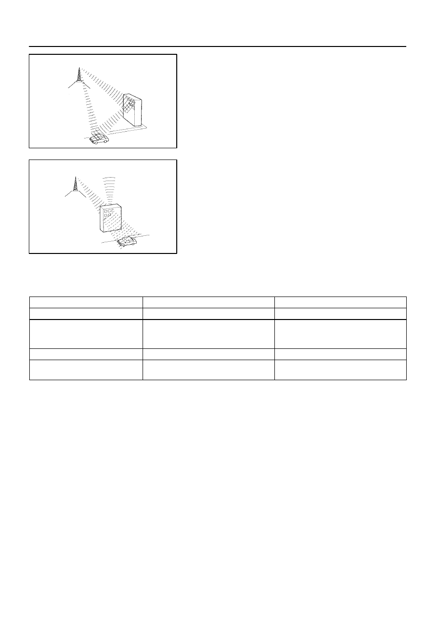
Multi–path:
BE2821
Fade Out:
–
DIAGNOSTICS
NAVIGATION SYSTEM
DI–2175
2369
(2)
Multi–path
A radio signal can sometimes be reflected by an ob-
struction in its path. When this occurs, the reflected
signal may interfere with the direct signal sent from
the transmitter. This phenomenon is known as ”Mul-
ti–path”.
(3)
Fade out
FM radio frequency is higher than AM. Therefore, it
is more likely to be reflected by large obstructions
such as tall buildings or mountains. For this reason,
the FM signal will gradually weaken or disappear
when the vehicle is behind such obstructions. This
phenomenon is known as ”fade out”.
(d)
Noise problem
It is very important for a technician to understand the specifics of the noise problem. To diagnose the
symptom, use the table below.
Radio Frequency
Noise occurrence condition
Presumable cause
AM
Noise occurs in a specified area
Foreign noise
AM
Noise occurs when listening to an intermittent
broadcast
An identical program transmitted from multiple
towers can cause noise where the signals over-
lap
AM
Noise occurs only at night
Music beat from a far–off broadcast
FM
Noise occurs while driving in a specified area
Multi–path or phasing noise resulting from a
change in FM frequency
HINT:
If the noise does not fall into any category in the table above, determine the cause using ”Radio reception
problems” above. Refer to the multi–path and phasing sections.