Toyota Sequoia (2005). Manual - part 484


  Главная      Automobile - Toyota     Toyota Sequoia - Repair manual 2005 year


поиск по сайту           правообладателям


содержание   ..  482  483  484  485   ..


Toyota Sequoia (2005). Manual - part 484
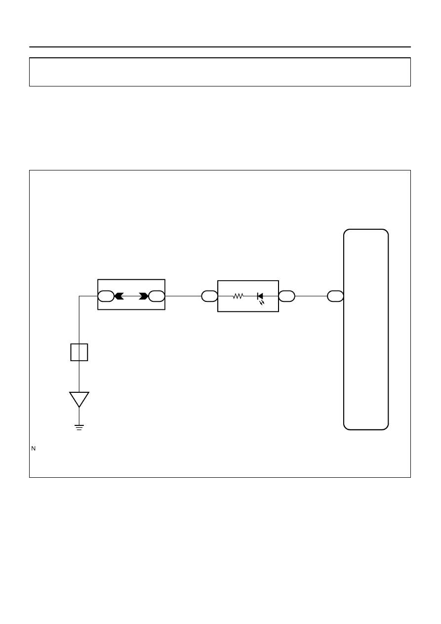


I18742

Body ECU

IE

W–B

IND

12

A

17

BR

J8
J/C

GR

9

1F

1D

6

C6

C5

Combination Meter

16

B5

Security

Instrument Panel J/B

DIAGNOSTICS

BODY CONTROL SYSTEM

DI–1731

1925

Theft deterrent indicator circuit

CIRCUIT DESCRIPTION

When the theft deterrent system is preparing to set, this circuit turns on the indicator light. When the system
has been set, it continually turns the indicator light on for 1 second and turns it off for 1 second, and thus
blinking the indicator light. 
This theft deterrent indicator sends a key judgment of the immobilizer to the transponder key ECU.

WIRING DIAGRAM

DI579–09

DI–1732

DIAGNOSTICS

BODY CONTROL SYSTEM

1926

INSPECTION PROCEDURE

HINT:
When using the hand–held tester, start the inspection from step 1 and when not using the hand–held tester,
start from step 2.

1

Check theft deterrent indicator using hand–held tester.

PREPARATION:
(a)

Connect the hand–held tester to the DLC3.

(b)

Turn the ignition switch ON.

CHECK:
According to the display on the tester, perform the ”ACTIVE TEST”.
BODY ECU:

Item

Test Details

Diagnostic Note

SECURITY INDIC

Turn security indicator light ON/OFF

OK:

The theft deterrent indicator light flashes or goes off correctly when operating it through the
hand–held tester.

OK

Proceed to next circuit inspection shown in
problem symptoms table (See page 

DI–1686

).

NG

2

Check theft deterrent indicator (See page 

DI–1608

).

NG

Replace combination meter.

OK

DIAGNOSTICS

BODY CONTROL SYSTEM

DI–1733

1927

3

Check wire harness and connector between theft deterrent indicator (combina-
tion meter) and body ECU, theft deterrent indicator (

combination meter

) and body

ground (See page 

IN–35

).

NG

Repair or replace wire harness or connector.

OK

Proceed to next circuit inspection shown in
problem symptoms table
(See page 

DI–1686

).

I18735

1

Body ECU

T1
Theft Deterrent Horn

IA1

14

R–G

B7

1

SH

R–G

DI–1734

DIAGNOSTICS

BODY CONTROL SYSTEM

1928

Theft deterrent horn circuit

CIRCUIT DESCRIPTION

During warning of the theft deterrent system, the body ECU activates the theft deterrent horn.

WIRING DIAGRAM

DI57A–10


содержание   ..  482  483  484  485   ..