Toyota Sequoia (2005). Manual - part 473


  Главная      Automobile - Toyota     Toyota Sequoia - Repair manual 2005 year


поиск по сайту           правообладателям


содержание   ..  471  472  473  474   ..


Toyota Sequoia (2005). Manual - part 473


DIAGNOSTICS

BODY CONTROL SYSTEM

DI–1687

1881

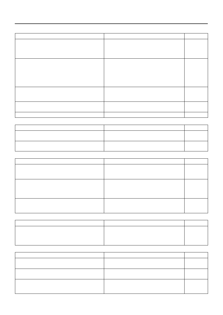
WIRELESS DOOR LOCK CONTROL

Symptom

Suspected Area

See page

All functions of wireless door lock control system do not operate.

1. Transmitter

2. Wireless door lock receiver circuit

3. Key unlock warning switch circuit

4. Body ECU

BE–99

DI–1737

DI–1715

IN–35

Lock (or unlock) function does not operate.

1. Door unlock detection switch circuit (Driver’s)

                                                      (Passenger’s)

                                                      (Rear Door)

                                                      (Back Door)

2. Any door ECU

3. Body ECU

DI–1791

DI–1829

DI–1723

DI–1869

IN–35

IN–35

Automatic lock function operates even if any door is opened within

30 seconds after all doors are unlocked by wireless door lock

control system.

1. Door courtesy light switch circuit

2. Any door ECU

3. Body ECU

DI–1728

IN–35

IN–35

Wireless door lock function operates, but the buzzer does not

sound.

1. Wireless door lock buzzer circuit

2. Body ECU

DI–1741

IN–35

Buzzer sounds, but wireless door lock function does not operate.

Body ECU

IN–35

REAR WIPER AND WASHER

Symptom

Suspected Area

See page

Rear wiper does not operate.

1. Rear wiper switch and motor circuit

2. Body ECU

DI–1704

IN–35

Rear washer does not operate.

1. Rear washer switch and motor circuit

2. Body ECU

DI–1704

IN–35

LIGHT CONTROL

Symptom

Suspected Area

See page

Automatic light control does not operate.

1. Automatic light control sensor circuit

2. Light control switch circuit

3. Body ECU

DI–1753

DI–1750

IN–35

Auto turn–off does not operate.

1. Door courtesy light switch circuit (Driver side)

2. Ignition switch 

3. Driver door ECU

4. Body ECU

DI–1728

BE–24

IN–35

IN–35

Daytime running light function does not operate.

1. Daytime running light relay circuit

2. Parking brake switch circuit

3. Body ECU

DI–1712

DI–1744

IN–35

FOG LIGHT

Symptom

Suspected Area

See page

Fog lights do not come on.

1. Bulb

2. FOG fuse

3. Fog light relay and switch circuit

4. Body ECU

BE–14

DI–1710

IN–35

OTHERS

Symptom

Suspected Area

See page

Illuminated entry function does not operate.

1. Illumination circuit

2. Body ECU

DI–1759

IN–35

All functions of the body control system do not operate.

1. Power source circuit

2. Body ECU

DI–1700

IN–35

Remote control mirror does not operate.

(w/ Driving position memory)

1. Remote control mirror switch circuit

2. Driving position memory switch circuit

3. Body ECU

DI–1767

DI–1772

IN–35

DI1OG–31

I27698

B5

B6

B7

BODY CONTROL ECU:

DI–1688

DIAGNOSTICS

BODY CONTROL SYSTEM

1882

TERMINALS OF ECU

Symbols (Terminals No.)

Wiring Color

Terminal Description

Condition

Specified Condition

KSW – GND1

(B5–13 – B6–6)

Y–G – W–B

Key unlock warning

switch signal

Key unlock warning switch ON

(Key inserted)

Below 1 V

KSW – GND1

(B5–13 – B6–6)

Y–G – W–B

Key unlock warning

switch signal

Key unlock warning switch OFF

(Key not inserted)

10 to 14 V

KSW2 – GND1 

(B5–15 – B6–6)

Y–G – W–B

Key unlock warning

switch signal (Immobi-

lizer)

Key unlock warning switch ON

(Key inserted)

Below 1 V

KSW2 – GND1 

(B5–15 – B6–6)

Y–G – W–B

Key unlock warning

switch signal (Immobi-

lizer)

Key unlock warning switch OFF

(Key not inserted)

10 to 14 V

HR – GND1 

(B7–18 – B6–6)

W–R – W–B

Horn switch signal

Horn switch ON

Below 1 V

HR – GND1 

(B7–18 – B6–6)

W–R – W–B

Horn switch signal

Horn switch OFF

10 to 14 V

BDN – GND1 

(B6–15 – B6–6)

P–L – W–B

Back door power win-

dow motor (DOWN)

Back door power window switch

DOWN position

Below 1 V

BDN – GND1 

(B6–15 – B6–6)

P–L – W–B

Back door power win-

dow motor (DOWN)

Back door power window switch

OFF or UP position

10 to 14 V

BUP – GND1 

(B6–14 – B6–6)

W – W–B

Back door power win-

dow motor (UP)

Back door power window switch

UP position

Below 1 V

BUP – GND1 

(B6–14 – B6–6)

W – W–B

Back door power win-

dow motor (UP)

Back door power window switch

OFF or DOWN position

10 to 14 V

ACC – GND1 

(B7–10 – B6–6)

GR – W–B

Ignition switch (ACC)

Ignition switch OFF

Below 1 V

ACC – GND1 

(B7–10 – B6–6)

GR – W–B

Ignition switch (ACC)

Ignition switch ACC or ON

10 to 14 V

BECU – GND1 

(B6–5 – B6–6)

W–R – W–B

Battery

Always

10 to 14 V

RLCY – GND1 

(B7–7 – B6–6)

R–W – W–B

Courtesy light switch

(Rear LH)

Rear LH door courtesy light

switch ON (Open)

Below 1 V

RLCY – GND1 

(B7–7 – B6–6)

R–W – W–B

Courtesy light switch

(Rear LH)

Rear LH door courtesy light

switch OFF (Closed)

10 to 14 V

RRCY – GND1 

(B5–8 – B6–6)

R–W – W–B

Courtesy light switch

(Rear RH)

Rear RH door courtesy light

switch ON (Open)

Below 1 V

RRCY – GND1 

(B5–8 – B6–6)

R–W – W–B

Courtesy light switch

(Rear RH)

Rear RH door courtesy light

switch OFF (Closed)

10 to 14 V

PCTY – GND1 

(B5–22 – B6–6)

LG–B – W–B

Courtesy light switch

(Front RH)

Passenger door courtesy light

switch ON (Open)

Below 1 V

DIAGNOSTICS

BODY CONTROL SYSTEM

DI–1689

1883

PCTY – GND1 

(B5–22 – B6–6)

LG–B – W–B

Courtesy light switch

(Front RH)

Passenger door courtesy light

switch OFF (Closed)

10 to 14 V

LSWL – GND1 

(B7–24 – B6–6)

P–L – W–B

Door unlock detection

switch (Rear LH)

Rear LH door unlock detection

switch ON (Unlocked)

Below 1 V

LSWL – GND1 

(B7–24 – B6–6)

P–L – W–B

Door unlock detection

switch (Rear LH)

Rear LH door unlock detection

switch OFF (Locked)

10 to 14 V

DCTY – GND1 

(B7–12 – B6–6)

GR–R – W–B

Courtesy light switch

(Front LH)

Driver door courtesy light switch

ON (Open)

Below 1 V

DCTY – GND1 

(B7–12 – B6–6)

GR–R – W–B

Courtesy light switch

(Front LH)

Driver door courtesy light switch

OFF (Closed)

10 to 14 V

LSWR – GND1 

(B5–21 – B6–6)

P–B – W–B

Door unlock detection

switch (Rear RH)

Rear RH door unlock detection

switch ON (Unlocked)

Below 1 V

LSWR – GND1 

(B5–21 – B6–6)

P–B – W–B

Door unlock detection

switch (Rear RH)

Rear RH door unlock detection

switch OFF (Locked)

10 to 14 V

HORN – GND1 

(B5–26 – B6–6)

B–Y – W–B

Horn switch signal

Horn switch OFF

10 to 14 V

HORN – GND1 

(B5–26 – B6–6)

B–Y – W–B

Horn switch signal

Horn switch ON

Below 1 V

BDR – GND1 

(B6–2 – B6–6)

L–W – W–B

Battery

Always

10 to 14 V

GND1 – Body ground 

(B6–6 – Body ground)

W–B – Body ground

Ground

Always

Below 1 V

RWLS – GND1 

(B5–6 – B6–6)

Y–B – W–B

Rear wiper switch sig-

nal (ON)

Rear wiper switch ON

Below 1 V

RWLS – GND1 

(B5–6 – B6–6)

Y–B – W–B

Rear wiper switch sig-

nal (ON)

Rear wiper switch OFF or INT

10 to 14 V

RWC1 – GND1 

(B5–7 – B6–6)

G–B – W–B

Rear wiper switch sig-

nal (INT)

Rear wiper switch INT

Below 1 V

RWC1 – GND1 

(B5–7 – B6–6)

G–B – W–B

Rear wiper switch sig-

nal (INT)

Rear wiper switch OFF

10 to 14 V

ACTD – GND1 

(B7–2 – B6–6)

R–B – W–B

Door lock motor (Front

LH)

Power door lock not operating or

operating to UNLOCK

Below 1 V

ACTD – GND1 

(B7–2 – B6–6)

R–B – W–B

Door lock motor (Front

LH)

Power door lock not operating to

LOCK

10 to 14 V

IND – GND1 

(B5–16 – B6–6)

GR – W–B

Security indicator light

Security indicator is off

Below 1 V

IND – GND1 

(B5–16 – B6–6)

GR – W–B

Security indicator light

Security indicator light is on

10 to 14 V

SH – GND1 

(B7–1 – B6–6)

R–G – W–B

Theft deterrent horn

signal

Security horn does not sound

Below 1 V

SH – GND1 

(B7–1 – B6–6)

R–G – W–B

Theft deterrent horn

signal

Security horn sounds

10 to 14 V

HRLY – GND1 

(B7–8 – B6–6)

LG–R – W–B

HEAD relay signal

HEAD relay ON

Below 1 V

HRLY – GND1 

(B7–8 – B6–6)

LG–R – W–B

HEAD relay signal

HEAD relay OFF

10 to 14 V

TRLY – GND1 

(B7–11 – B6–6)

LG – W–B

Taillight relay signal

Taillight relay ON

Below 1 V

TRLY – GND1 

(B7–11 – B6–6)

LG – W–B

Taillight relay signal

Taillight relay OFF

10 to 14 V

DI–1690

DIAGNOSTICS

BODY CONTROL SYSTEM

1884

HCTY – GND1 

(B7–14 – B6–6)

L–W – W–B

Engine hood courtesy

switch signal

Hood courtesy light switch ON

(Open)

Below 1 V

HCTY – GND1 

(B7–14 – B6–6)

L–W – W–B

Engine hood courtesy

switch signal

Hood courtesy light switch OFF

(Close)

10 to 14 V

WIG – GND1 

(B7–5 – B6–6)

L–Y – W–B

Ignition Switch (IG)

Ignition switch LOCK

Below 1 V

WIG – GND1 

(B7–5 – B6–6)

L–Y – W–B

Ignition Switch (IG)

Ignition switch ON

10 to 14 V

IG – GND1 

(B7–6 – B6–6)

B–R – W–B

Ignition Switch (IG)

Ignition switch LOCK

Below 1 V

IG – GND1 

(B7–6 – B6–6)

B–R – W–B

Ignition Switch (IG)

Ignition switch ON

10 to 14 V

RWW – GND1 

(B7–4 – B6–6)

G–B – W–B

Rear washer switch

(ON)

Rear washer switch ON

Below 1 V

RWW – GND1 

(B7–4 – B6–6)

G–B – W–B

Rear washer switch

(ON)

Rear washer switch OFF

10 to 14 V

ACT+ – GND1 

(B5–1 – B6–6)

L–R – W–B

Door lock motor (UN-

LOCK)

Power door lock not operating or

operating to UNLOCK

Below 1 V

ACT+ – GND1 

(B5–1 – B6–6)

L–R – W–B

Door lock motor (UN-

LOCK)

Power door lock operating to

LOCK

10 to 14 V

ACT– – GND1 

(B5–10 – B6–6)

L–B – W–B

Door lock motor

(LOCK)

Power door lock not operating or

operating to LOCK

Below 1 V

ACT– – GND1 

(B5–10 – B6–6)

L–B – W–B

Door lock motor

(LOCK)

Power door lock operating to UN-

LOCK twice

10 to 14 V

MPX1

(B7–22)

W–L

Multiplex communica-

tion signal

Multiplex communication circuit

MPX2 (*2)

(B5–24)

L–Y

Multiplex communica-

tion signal

Multiplex communication circuit

MPX3

(B7–20)

G–O

Multiplex communica-

tion signal

Multiplex communication circuit

ILE – GND1 

(B7–3 – B6–6)

W – W–B

Illumination

Map Light is off

Below 1 V

ILE – GND1 

(B7–3 – B6–6)

W – W–B

Illumination

Map Light is on

10 to 14 V

PRG – GND1 

(B5–5 – B6–6)

V – W–B

Wireless transmitter

signal ground

Wireless door look receiver com-

munication circuit

RDA – GND1 

(B5–4 – B6–6)

R–G – W–B

Wireless transmitter

signal input

Wireless door lock control sys-

tem is operated

Below 1 V

RDA – GND1 

(B5–4 – B6–6)

R–G – W–B

Wireless transmitter

signal input

Wireless door lock control sys-

tem is not operated

10 to 14 V

HU – GND1 

(B6–11 – B6–6)

Y–R – W–B

Headlight dimmer

switch (HI)

Headlight dimmer switch position

is Hi beam or FLASH

Below 1 V

HU – GND1 

(B6–11 – B6–6)

Y–R – W–B

Headlight dimmer

switch (HI)

Headlight dimmer switch position

is not Hi beam or FLASH

10 to 14 V

HF – GND1 

(B6–8 – B6–6)

R–L – W–B

Headlight dimmer

switch (FLASH)

Headlight dimmer switch position

is FLASH

Below 1 V

HF – GND1 

(B6–8 – B6–6)

R–L – W–B

Headlight dimmer

switch (FLASH)

Headlight dimmer switch position

is not FLASH

10 to 14 V

TAIL – GND1 

(B6–7 – B6–6)

G – W–B

Light control switch

(TAIL)

Light control switch TAIL or

HEAD

Below 1 V


содержание   ..  471  472  473  474   ..