содержание .. 430 431 432 433 ..
Toyota Sequoia (2005). Manual - part 432
I28701
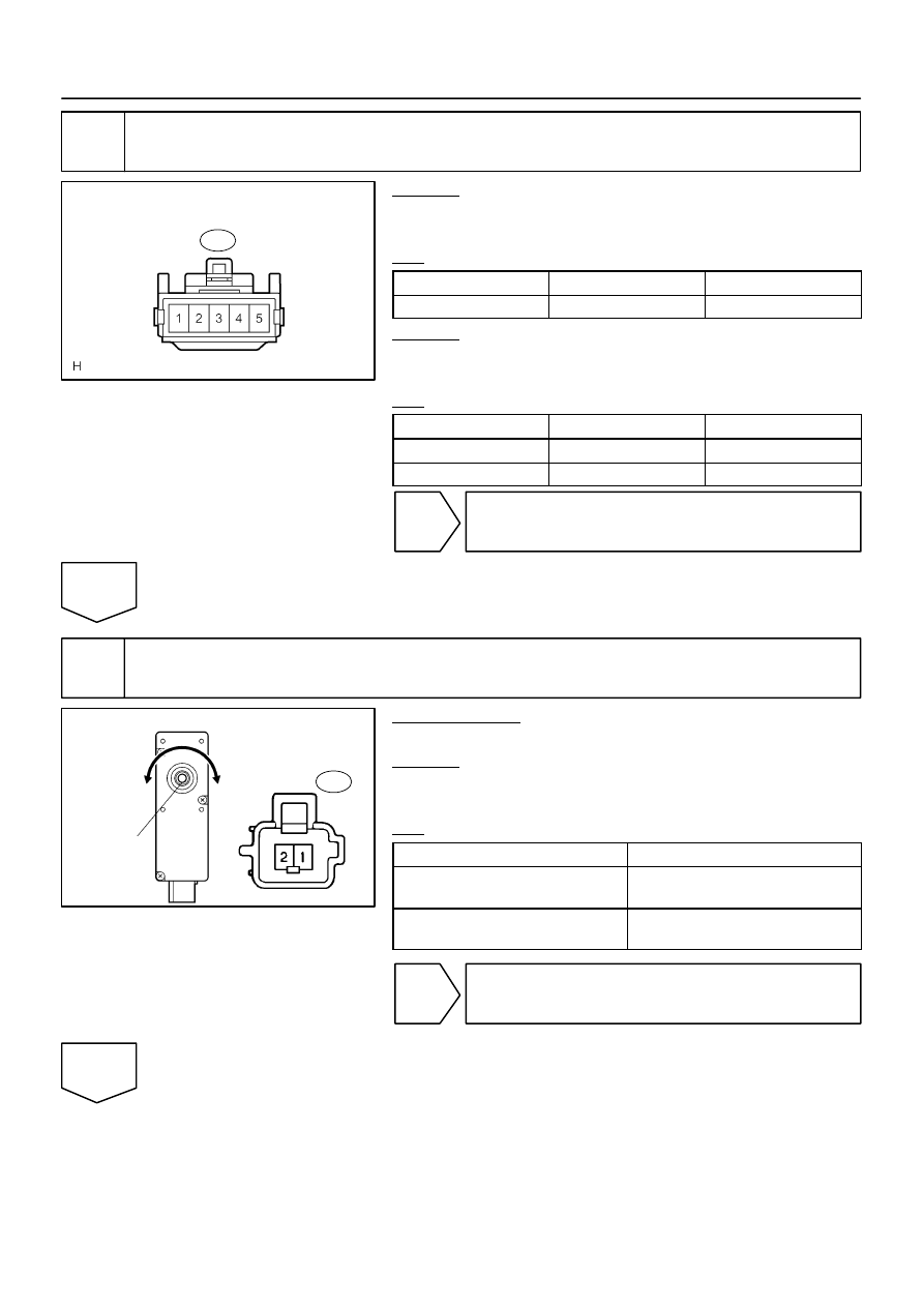
Wire Harness Side:
Lumbar Support Control Switch
L4
I28702
Lumbar Support Control Motor
Clockwise
Counter-
clockwise
Driving Axis
L3
–
DIAGNOSTICS
POWER SEAT CONTROL SYSTEM (w/ Driving Position
Memory)
DI–1523
1717
3
Check harness and connector (Power source).
CHECK:
Measure the voltage of each terminal of the wire harness side
connectors.
OK:
Tester Connection
Condition
Specified Condition
L4–3 – Body ground
Always
10 to 14 V
CHECK:
Measure the resistance of each terminal, as shown in the il-
lustration and table.
OK:
Tester Connection
Condition
Specified Condition
L4–2 – Body ground
Always
Below 1
Ω
L4–5 – Body ground
Always
Below 1
Ω
NG
Repair or replace harness or connector.
OK
4
Inspect lumbar support control motor.
PREPARATION:
Remove the lumbar support control motor (See page
CHECK:
Check that the motor rotates smoothly when the battery is con-
nected to the lumbar support control motor connector terminals.
OK:
Measurement Condition
Operational Direction
Battery positive (+)
→
1
Battery negative (–)
→
2
Clockwise
Battery positive (+)
→
2
Battery negative (–)
→
1
Counterclockwise
NG
Replace lumbar support control motor
(See page
OK