Toyota Sequoia (2005). Manual - part 431


  Главная      Automobile - Toyota     Toyota Sequoia - Repair manual 2005 year


поиск по сайту           правообладателям


содержание   ..  429  430  431  432   ..


Toyota Sequoia (2005). Manual - part 431


I27717

DIAGNOSTICS

POWER SEAT CONTROL SYSTEM (w/ Driving Position 
Memory)

DI–1519

1713

INSPECTION PROCEDURE

1

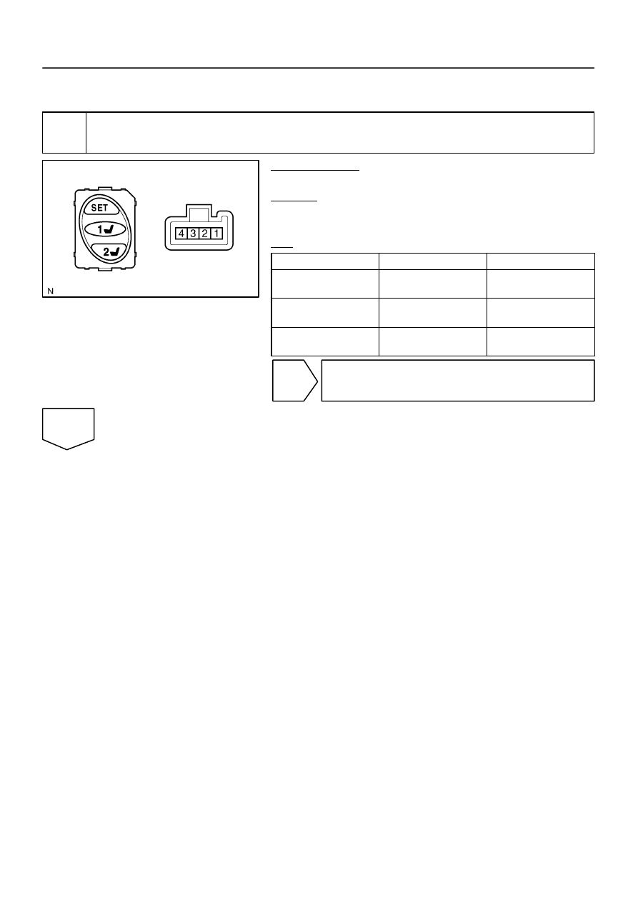
Inspect seat memory switch.

PREPARATION:
Disconnect the seat memory switch connector.
CHECK:
Measure the resistance of each terminal, as shown in the il-
lustration and table.
OK:

Tester Connection

Switch Position

Specified Condition

1 – 4

SET switch OFF 

 ON

10 k

 or higher


Below 1 

2 – 4

Memory switch 1 OFF 

ON

10 k

 or higher


Below 1 

3 – 4

Memory switch 2 OFF 

ON

10 k

 or higher


Below 1 

NG

Replace seat memory switch.

OK

I27700

B6

Body ECU Wire Harness View:

MM

M1

M2

DI–1520

DIAGNOSTICS

POWER SEAT CONTROL SYSTEM (w/ Driving Position 
Memory)

1714

2

Check harness and connector (Body ECU & seat memory switch – body ground).

PREPARATION:
(a)

Reconnect the seat memory switch connector.

(b)

Disconnect the B6 body ECU connector.

CHECK:
Measure the resistance of each terminal, as shown in the il-
lustration and table.
OK:

Tester Connection 

(Symbol)

Switch Position

Specified Condition

B6–23 (M1) – 

Body ground

Memory switch 1 OFF 

ON

10 k

 or higher


Below 1 

B6–24 (MM) – 

Body ground

SET switch OFF 

 ON

10 k

 or higher


Below 1 

B6–22 (M2) – 

Body ground

Memory switch 2 OFF 

ON

10 k

 or higher


Below 1 

NG

Repair or replace harness or connector.

OK

Proceed to next circuit inspection shown in
problem symptoms table (See page 

DI–1508

).

I28448

PWR SEAT

Instrument Panel J/B

ALT

16

1

1

2

L–O

L–O

BI2

9

L4
Lumbar Support Control 
Switch (Driver’s Seat)

3

1

2

4

5

Rear

Front

W

W–B

W–B

BH

Battery

L

R

1

L

A

A

BI2

1G

1L

F10
FL Block

J24 J/C

L3
Lumbar Support 
Control Motor

L–O

J24 J/C

J/C

L–O

J31

J32

3

R

B

H

B

5

8

C

G

B

B

B

2

W–B

W–B

E2

E

DIAGNOSTICS

POWER SEAT CONTROL SYSTEM (w/ Driving Position 
Memory)

DI–1521

1715

Lumbar support control switch circuit

CIRCUIT DESCRIPTION

The lumbar support control switch that controls lumbar support is connected to the lumbar support control
motor via a wire harness. This circuit can freely operate regardless of the condition of the ECU.

WIRING DIAGRAM

DIDE9–01

I28700

HOLD (Front)

RELEASE (Rear)

DI–1522

DIAGNOSTICS

POWER SEAT CONTROL SYSTEM (w/ Driving Position 
Memory)

1716

INSPECTION PROCEDURE

1

Check fuse (PWR SEAT).

PREPARATION:
Remove the PWR SEAT fuse from the instrument panel J/B.
CHECK:
Measure the resistance.
OK:

Below 1 

NG

Replace fuse.

OK

2

Inspect lumbar support control switch.

PREPARATION:
Disconnect the lumbar support control switch connector.
CHECK:
Measure the resistance of each terminal, as shown in the il-
lustration and table.
OK:

Tester Connection

Switch Position

Specified Condition

1 – 2

HOLD (Front)

Below 1 

3 – 4

HOLD (Front)

Below 1 

1 – 2

OFF

Below 1 

4 – 5

OFF

Below 1 

1 – 3

RELEASE (Rear)

Below 1 

4 – 5

RELEASE (Rear)

Below 1 

NG

Replace lumbar support control switch assy
(See page 

BO–112

).

OK


содержание   ..  429  430  431  432   ..