содержание .. 383 384 385 386 ..
Toyota Sequoia (2005). Manual - part 385
H23821
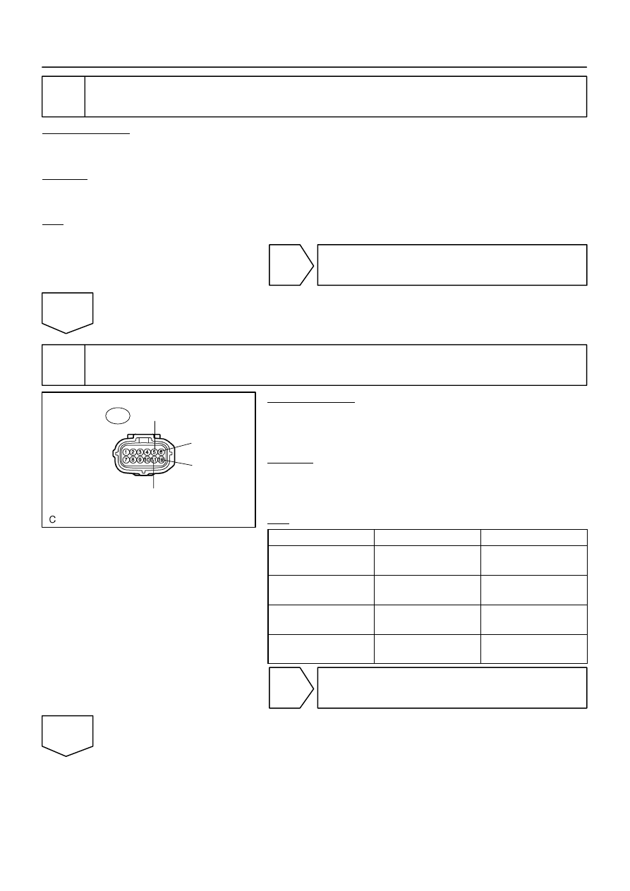
SVC1
SVC2
SVC4
SVC3
O7
Occupant Classification ECU:
–
DIAGNOSTICS
SUPPLEMENTAL RESTRAINT SYSTEM
DI–1335
1529
2
Check connection of connectors.
PREPARATION:
(a)
Turn the ignition switch to the LOCK position.
(b)
Disconnect the negative (–) terminal cable from the battery, and wait for at least 90 seconds.
CHECK:
Check that the connectors are properly connected to the occupant classification ECU and the occupant clas-
sification sensors.
OK:
The connectors are connected securely.
NG
Connect connectors, then go to step 1.
OK
3
Check seat wire No. 1 (short to B+).
PREPARATION:
(a)
Disconnect the connector from the occupant classifica-
tion ECU and the 4 occupant classification sensors.
(b)
Connect the negative (–) terminal cable to the battery.
CHECK:
(a)
Turn the ignition switch to the ON position.
(b)
Measure the voltage according to the value(s) in the table
below.
OK:
Tester Connection
Condition
Specified Condition
O7–5 (SVC3) –
Body ground
Ignition switch ON
Below 1 V
O7–6 (SVC4) –
Body ground
Ignition switch ON
Below 1 V
O7–11 (SVC1) –
Body ground
Ignition switch ON
Below 1 V
O7–12 (SVC2) –
Body ground
Ignition switch ON
Below 1 V
NG
Repair or replace seat wire No. 1.
OK