содержание .. 382 383 384 385 ..
Toyota Sequoia (2005). Manual - part 384
C84211
H24024
H24005
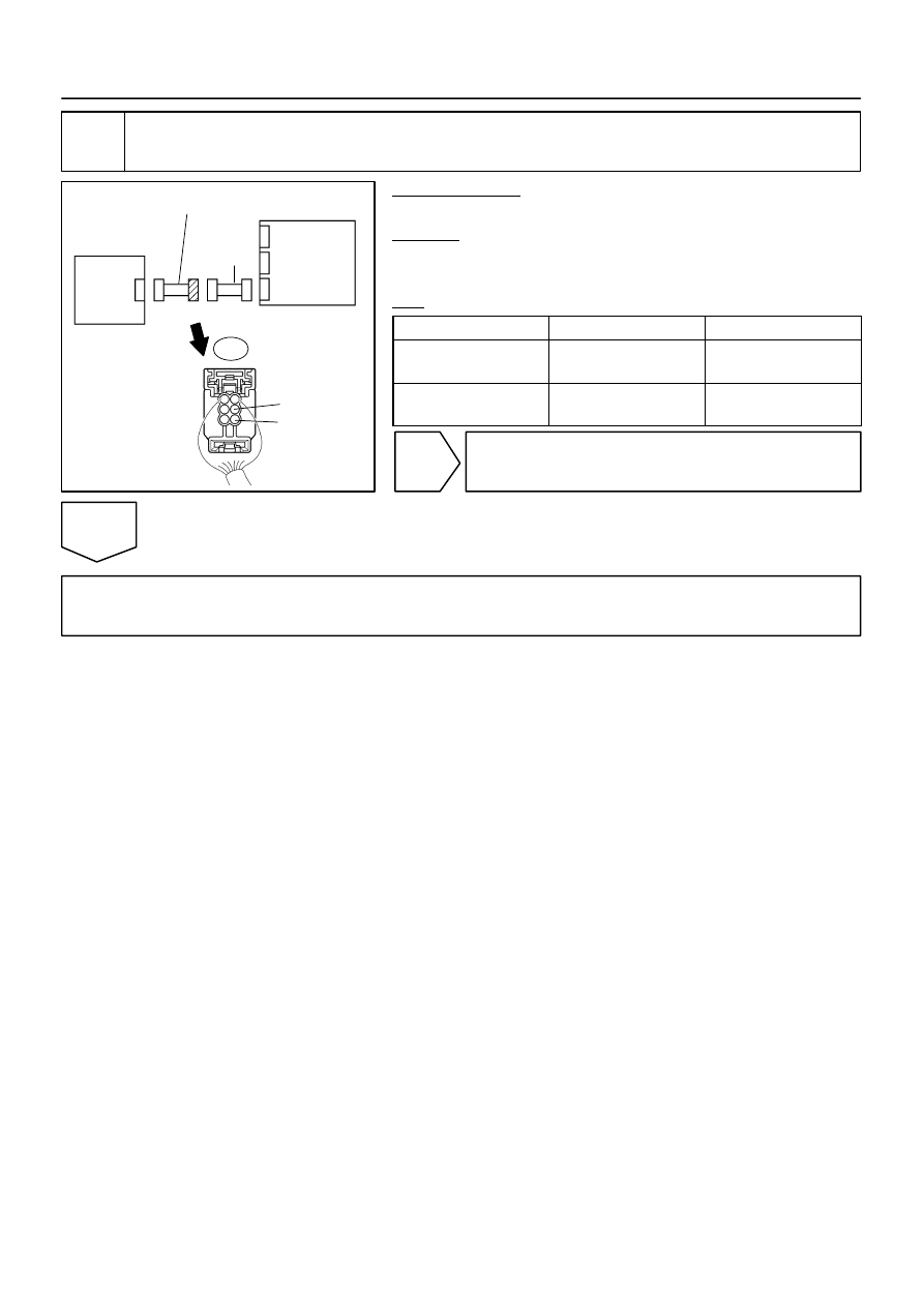
Occupant
Classification
ECU
Airbag
Sensor
Assembly
A
FSR+
FSR–
B
C
D
E
F
BL1
Seat Wire No. 1
Floor Wire
–
DIAGNOSTICS
SUPPLEMENTAL RESTRAINT SYSTEM
DI–1331
1525
16
Check seat wire No. 1 (short to ground).
PREPARATION:
Disconnect the seat wire No. 1 connector from the floor wire.
CHECK:
Measure the resistance according to the value(s) in the table
below.
OK:
Tester Connection
Condition
Specified Condition
BL1–3 (FSR+) –
Body ground
Always
1 M
Ω
or higher
BL1–5 (FSR–) –
Body ground
Always
1 M
Ω
or higher
NG
Repair or replace seat wire No. 1.
OK
Repair or replace floor wire.