содержание .. 174 175 176 177 ..
Toyota Sequoia (2005). Manual - part 176
A01995 A15196
A15197
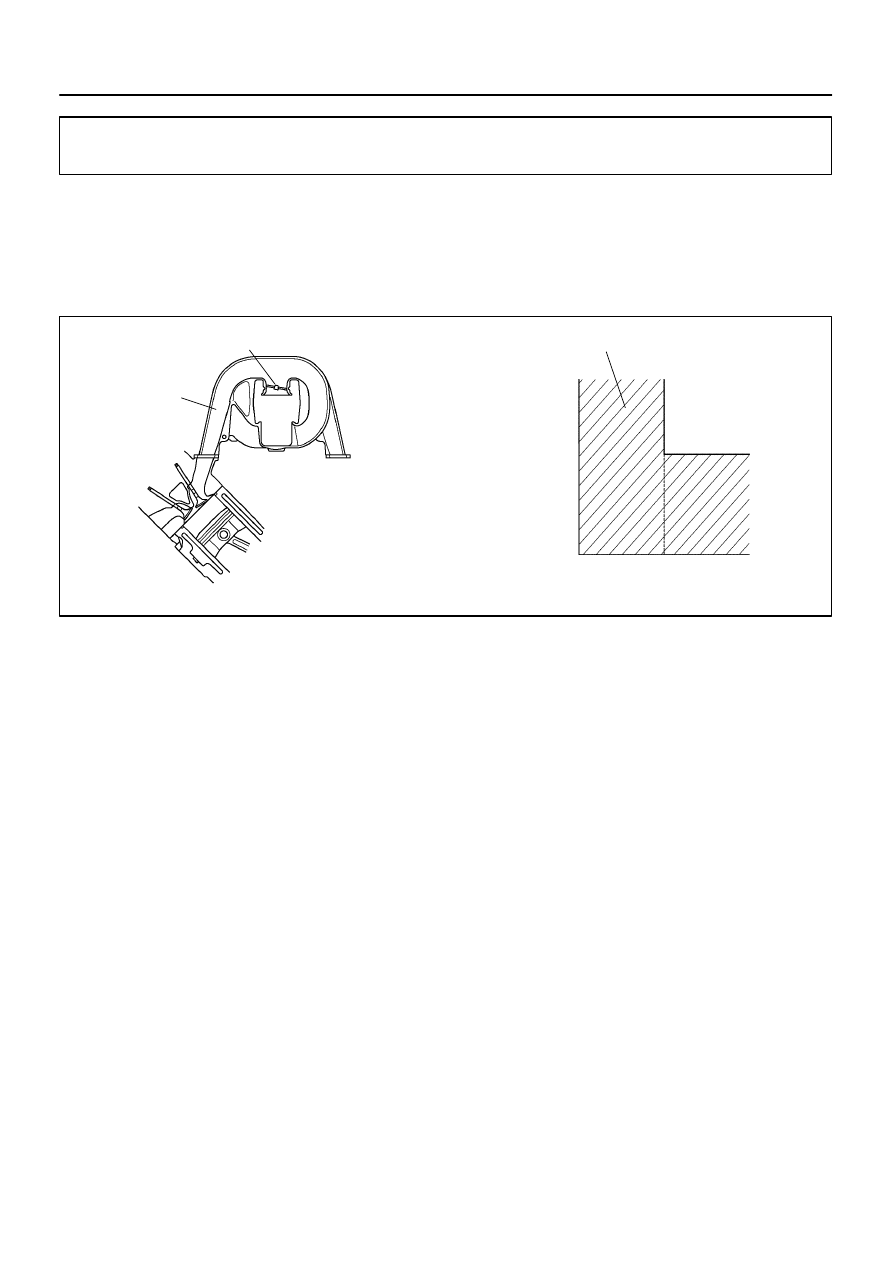
IACV
IACV closed (VSV: ON)
Intake
Manifold
60
°
Throttle valve
opening angle
Engine speed (rpm)
4,700
–
DIAGNOSTICS
ENGINE
DI–499
693
IACV Control Circuit
CIRCUIT DESCRIPTION
This circuit opens and closes the Intake Air Control Valve (IACV) in response to the engine load in order to
increase the intake efficiency (ACIS: Acoustic Control Induction System).
When the engine speed is 4,700 rpm or more and the throttle valve opening angle is 60
°
or more, the VSV
is OFF, so the is IACV open. All the other times, the ECM turns the VSV ON and closes the IACV.
DIDG0–01