Toyota Sequoia (2005). Manual - part 175


  Главная      Automobile - Toyota     Toyota Sequoia - Repair manual 2005 year


поиск по сайту           правообладателям


содержание   ..  173  174  175  176   ..


Toyota Sequoia (2005). Manual - part 175


B17411

+B

E1

(+)

(–)

E6

E4

B17411

IGSW (+)

E4

DIAGNOSTICS

ENGINE

DI–495

689

INSPECTION PROCEDURE

1

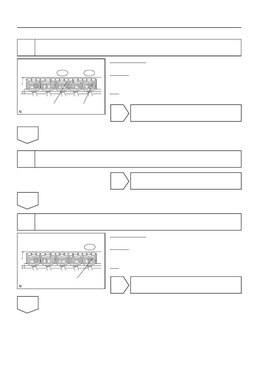
Check voltage between terminals 

+

B and E1 of ECM connector.

PREPARATION:
Turn the ignition switch ON.
CHECK:
Measure the voltage between terminals 

+

B and E1 of the ECM

connectors.
OK:

Standard: 9 to 14 V

OK

Proceed to next circuit inspection shown in the
Problem symptoms table (See page 

BE–2

).

NG

2

Check for open in harness and connector between terminal E1 of ECM and body
ground (See page 

IN–35

).

NG

Repair or replace harness or connector.

OK

3

Check voltage between terminal IGSW of ECM connector and body ground.

PREPARATION:
Turn the ignition switch ON.
CHECK:
Measure the voltage between terminal IGSW of the ECM con-
nector and body ground.
OK:

Standard: 9 to 14 V

OK

Go to step 6.

NG

A21560

IGN1

Instrument 
Panel J/B:

I08467

LOCK

ACC

ON

START

DI–496

DIAGNOSTICS

ENGINE

690

4

Check IGN1 fuse.

PREPARATION:
Remove the IGN1 fuse from the instrument panel J/B.
CHECK:
Check the resistance of the IGN1 fuse.
OK:

Below 1 

NG

Check for short in all harness and components
connected to IGN1 fuse.

OK

5

Check ignition switch (See page 

BE–24

).

PREPARATION:
(a)

Remove the lower finish panel.

(b)

Disconnect the ignition switch connector.

CHECK:
Check resistance between terminals.
OK:

Standard:

Switch Position

Terminal Condition

Specified Condition

LOCK

Always

10 k

 or more

ACC

1 – 3

Below 1 

ON

1 – 2 – 3

5 – 6

Below 1 

START

1 – 2

4 – 5 – 6

Below 1 

NG

Replace ignition switch.

OK

Check and repair harness and connector be-
tween IGN fuse and ECM.

B17411

MREL(+)

E4

Engine Room 
J/B:

A21381

EFI No. 1 
Fuse

DIAGNOSTICS

ENGINE

DI–497

691

6

Check voltage between terminal MREL of ECM connector and body ground.

PREPARATION:
Turn the ignition switch ON.
CHECK:
Measure the voltage between terminal MREL of the ECM con-
nector and body ground.
OK:

Standard: 9 to 14 V

NG

Replace ECM (See page 

SF–80

).

OK

7

Check EFI No. 1 fuse of engine room J/B.

PREPARATION:
Remove the EFI No. 1 fuse from the engine room J/B.
CHECK:
Check resistance of EFI No. 1 fuse.
OK:

Below 1 

NG

Check for short in all harness and components
connected to EFI No. 1 fuse.

OK

A19288

EFI Relay

B17417

E4

MREL

ECM Connector

DI–498

DIAGNOSTICS

ENGINE

692

8

Check EFI relay.

PREPARATION:
Remove the EFI relay from the engine room J/B.
CHECK:
Inspect the EFI relay.
OK:

Standard:

Terminal No.

Condition

Specified Condition

3 – 5

Always

10 K

 or higher

3 – 5

Apply B+ between 

terminals 1 and 2

Below 1  

NG

Replace EFI relay.

OK

9

Check for open and short in harness and connector between terminal MREL of
ECM and body ground.

PREPARATION:
Disconnect the E4 ECM connector.
CHECK:
Measure the resistance between the wire harness side connec-
tor and body ground.
OK:

Standard:

Tester Connection

Specified Condition

MREL (E4–8) – Body ground

Below 1 

NG

Repair or replace harness or connector.

OK

Check for intermittent problems
(See page 

DI–11

).


содержание   ..  173  174  175  176   ..