содержание .. 89 90 91 92 ..
Toyota Sequoia (2005). Manual - part 91
B17394
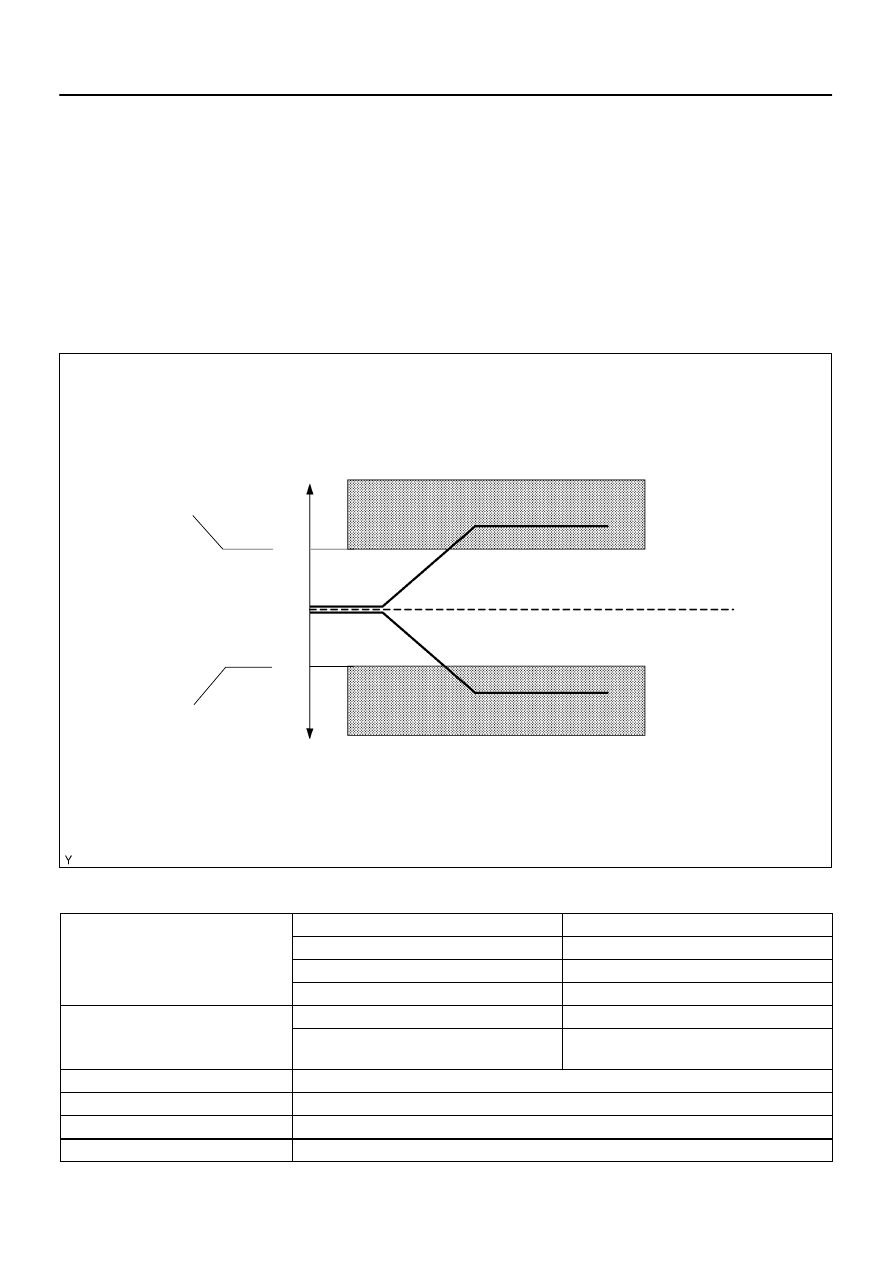
Fuel
Compensation
Amount
1.35
1.0
0.65
+35 (%):
Lean Malfunction Threshold
–35 (%):
Rich Malfunction Threshold
P0171, P0174:
P0172, P0175:
–
DIAGNOSTICS
ENGINE
DI–167
361
MONITOR DESCRIPTION
Under closed–loop fuel control, fuel injection volumes that deviate from those estimated by the ECM cause
changes in the long–term fuel trim compensation value. The long–term fuel trim is adjusted when there are
persistent deviations in the short–term fuel trim values. Deviations from the ECM’s estimated fuel injection
volumes also affect the average fuel trim learning value, which is a combination of the average short–term
fuel trim (fuel feedback compensation value) and the average long–term fuel trim (learning value of the air–
fuel ratio). If the average fuel trim learning value exceeds the malfunction thresholds, the ECM interprets
this a fault in the fuel system and sets a DTC.
Example:
The average fuel trim leaning value is more than +35 % or less than –35 %, the ECM interprets this as a fuel
system malfunction.
MONITOR STRATEGY
P0171
Fuel system lean (Bank 1)
R l t d DTC
P0172
Fuel system rich (Bank 1)
Related DTCs
P0174
Fuel system lean (Bank 2)
P0175
Fuel system rich (Bank 2)
Main sensors/components
Front oxygen sensor
Required sensors/components
Related sensors/components
Engine coolant temperature sensor, Mass air flow
meter, Crankshaft position sensor
Frequency of operation
Continuous
Duration
10 sec.
MIL operation
2 driving cycles
Sequence of operation
None