содержание .. 88 89 90 91 ..
Toyota Sequoia (2005). Manual - part 90
A19288
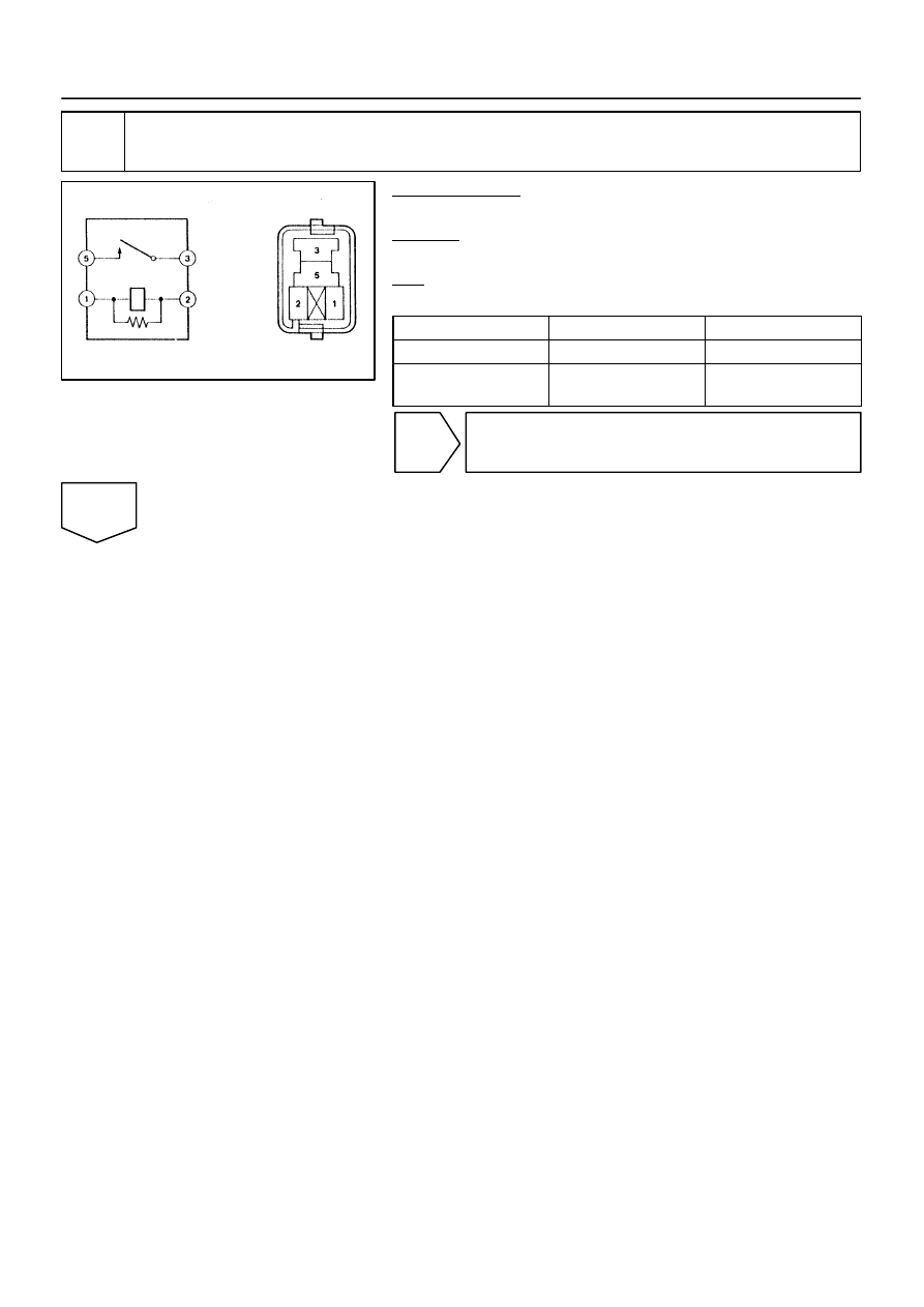
EFI Relay
–
DIAGNOSTICS
ENGINE
DI–163
357
16
Check EFI relay.
PREPARATION:
Remove the EFI relay from the engine room J/B.
CHECK:
Inspect the EFI relay.
OK:
Standard:
Terminal No.
Condition
Specified Condition
3 – 5
Always
10 K
Ω
or higher
3 – 5
Apply B+ between
terminals 1 and 2
Below 1
Ω
NG
Replace EFI relay.
OK