Toyota Tundra (2015 year). Manual - part 3034


  Index      Toyota     Toyota Tundra (2015 year) - Service and Repair Manual


Search            copyright infringement  


Content   ..  3032  3033  3034  3035   ..


Toyota Tundra (2015 year). Manual - part 3034
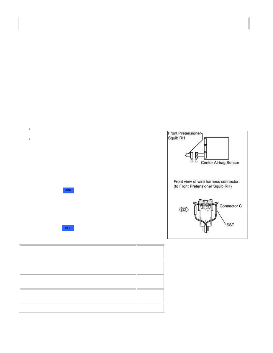


1.

CHECK FRONT SEAT OUTER BELT RH (FRONT PRETENSIONER SQUIB RH)

(a) Turn the ignition switch off.

(b) Disconnect the negative (-) terminal cable from the battery,

and wait for at least 90 seconds.

(c) Disconnect the connectors from the front seat outer belt RH.

CAUTION:

Never connect the tester to the front seat outer belt RH (front

pretensioner squib RH) for measurement, as this may lead to a
serious injury due to airbag deployment.

NOTICE:

(e) Connect the negative (-) terminal cable to the battery, and

wait for at least 2 seconds.

(f) Turn the ignition switch to ON, and wait for at least 60

seconds.

(g) Clear the DTCs 


.

(h) Turn the ignition switch off.

(i) Turn the ignition switch to ON, and wait for at least 60

seconds.

(j) Check for DTCs 


.

Result

RESULT

PROCEED

TO

DTC B1905, B1906, B1907 or B1908 is not output (for

Regular Cab)

A

DTC B1905, B1906, B1907 or B1908 is not output (for

Double Cab)

B

DTC B1905, B1906, B1907 or B1908 is not output (for

CrewMax)

C

DTC B1905, B1906, B1907 or B1908 is output

D

HINT:

Codes other than DTC B1905, B1906, B1907 and B1908 may be

output at this time, but they are not related to this check.

SUPPLEMENTAL RESTRAINT SYSTEM: AIRBAG SYSTEM: B1905/...

D

OK

A

REPLACE FRONT SEAT OUTER BELT ASSEMBLY RH

B

REPLACE FRONT SEAT OUTER BELT ASSEMBLY RH

C

REPLACE FRONT SEAT OUTER BELT ASSEMBLY RH

2.

CHECK CONNECTOR

(a) Turn the ignition switch off.

(b) Disconnect the negative (-) terminal cable from the battery, and wait for at least 90 seconds.

(c) Disconnect SST from connector C.

(d) Check that the No. 2 floor wire connector (on the front seat outer belt RH side) is not damaged.

OK:

REPLACE NO. 2 FLOOR WIRE

3.

CHECK NO. 2 FLOOR WIRE (FRONT PRETENSIONER SQUIB RH CIRCUIT)

SUPPLEMENTAL RESTRAINT SYSTEM: AIRBAG SYSTEM: B1905/...

OK

(a) Disconnect the connectors from the center airbag sensor.

(b) Connect the negative (-) terminal cable to the battery, and

wait for at least 2 seconds.

(c) Turn the ignition switch to ON.

(d) Measure the voltage according to the value(s) in the table

below.

Standard voltage:

TESTER CONNECTION

SWITCH

CONDITION

SPECIFIED

CONDITION

Q2-1 (R+) - Body

ground

Ignition switch ON

Below 1 V

Q2-2 (R-) - Body ground

(e) Turn the ignition switch off.

(f) Disconnect the negative (-) terminal cable from the battery,

and wait for at least 90 seconds.

(g) Measure the resistance according to the value(s) in the

table below.

Standard resistance:

TESTER CONNECTION

CONDITION

SPECIFIED CONDITION

Q2-1 (R+) - Q2-2 (R-)

Always

Below 1 Ω

(h) Release the activation prevention mechanism built into

connector B 


.

(i) Measure the resistance according to the value(s) in the table

below.

Standard resistance:

TESTER CONNECTION

CONDITION

SPECIFIED CONDITION

Q2-1 (R+) - Q2-2 (R-)

Always

1 MΩ or higher

Q2-1 (R+) - Body ground

Q2-2 (R-) - Body ground

NG

REPLACE NO. 2 FLOOR WIRE

SUPPLEMENTAL RESTRAINT SYSTEM: AIRBAG SYSTEM: B1905/...

4.

CHECK CENTER AIRBAG SENSOR

(a) Connect the connectors to the front seat outer belt RH and

the center airbag sensor.

(b) Connect the negative (-) terminal cable to the battery, and

wait for at least 2 seconds.

(c) Turn the ignition switch to ON, and wait for at least 60

seconds.

(d) Clear the DTCs stored in the memory 


.

(e) Turn the ignition switch off.

(f) Turn the ignition switch to ON, and wait for at least 60

seconds.

(g) Check the DTCs 


.

Result

RESULT

PROCEED

TO

DTC B1905, B1906, B1907 or B1908 is output (for

Column Shift Type)

A

DTC B1905, B1906, B1907 or B1908 is output (for Floor

Shift Type)

B

DTC B1905, B1906, B1907 or B1908 is not output

C

HINT:

Codes other than DTC B1905, B1906, B1907 and B1908 may be

output at this time, but they are not related to this check.

A

REPLACE CENTER AIRBAG SENSOR ASSEMBLY

B

REPLACE CENTER AIRBAG SENSOR ASSEMBLY

C

USE SIMULATION METHOD TO CHECK

SUPPLEMENTAL RESTRAINT SYSTEM: AIRBAG SYSTEM: B1905/...


Content   ..  3032  3033  3034  3035   ..