Toyota Tundra. Manual - part 963
 

  Index      Toyota     Toyota Tundra (2007-2010 year) - Service and Repair Manual


Search            copyright infringement  


Content   ..  961  962  963  964   ..


Toyota Tundra. Manual - part 963


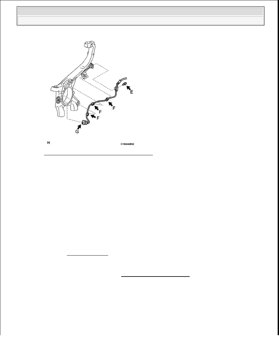
Fig. 155: Locating Harness Clamps With Bolts 
Courtesy of TOYOTA MOTOR SALES, U.S.A., INC. 

7. INSTALL FRONT WHEEL 

Torque: for Aluminum Wheel  

131 N*m (1336 kgf*cm, 97 ft.*lbf)  

for Steel Wheel  

209 N*m (2131 kgf*cm, 154 ft.*lbf)  

8. CONNECT CABLE TO NEGATIVE BATTERY TERMINAL 

9. CHECK SPEED SENSOR SIGNAL 

a. Check the speed sensor signal (see TEST MODE PROCEDURE ).  

REAR SPEED SENSOR 

COMPONENTS 

NOTE:

Some systems need to be initialized after the cable is reconnected (see 
INITIALIZATION ).


2009 Toyota Tundra 

2009 BRAKES Brake Control - Tundra


Fig. 156: Identifying Rear Speed Sensor Replacement Components With Torque Specifications 
Courtesy of TOYOTA MOTOR SALES, U.S.A., INC. 

REMOVAL 

1. DISCONNECT CABLE FROM NEGATIVE BATTERY TERMINAL 

2. REMOVE REAR WHEEL  

3. REMOVE REAR SPEED SENSOR LH 

a. Disconnect the speed sensor connector (labeled A).  

NOTE:

After the ignition switch is turned OFF, the navigation system 
requires approximately 90 seconds to record various types of 
memory and settings. As a result, after turning the ignition switch 
OFF, wait 90 seconds or more before disconnecting the cable from 
the negative (-) battery terminal.  

Some systems need to be initialized after the cable is reconnected 
(see INITIALIZATION ).  


2009 Toyota Tundra 

2009 BRAKES Brake Control - Tundra


b. Remove the nut (labeled B) and speed sensor (labeled C). 

Fig. 157: Locating Speed Sensor Connector And Nut 
Courtesy of TOYOTA MOTOR SALES, U.S.A., INC. 

4. REMOVE REAR SPEED SENSOR RH 

a. Disconnect the speed sensor connector (labeled A).  

b. Remove the nut (labeled B) and speed sensor (labeled C).  

5. REMOVE SKID CONTROL SENSOR WIRE 

a. Disconnect the sensor connector (labeled A).  

b. Detach the 7 clips (labeled B).  

c. Remove the bolt (labeled C).  

d. Remove the nut (labeled D) and skid control sensor wire. 

Fig. 158: Locating Sensor Connector Clips, Bolt And Nut 
Courtesy of TOYOTA MOTOR SALES, U.S.A., INC. 


2009 Toyota Tundra 

2009 BRAKES Brake Control - Tundra


Fig. 159: Locating Skid Control Sensor Wire 
Courtesy of TOYOTA MOTOR SALES, U.S.A., INC. 

INSTALLATION 

1. INSTALL SKID CONTROL SENSOR WIRE 

a. Install the sensor clamp with the nut (labeled A). 

Torque: 13 N*m (127 kgf*cm, 9 ft.*lbf)  

b. Install the sensor clamp with the bolt (labeled B). 

Torque: 13 N*m (127 kgf*cm, 9 ft.*lbf)  

c. Attach the 7 clips (labeled C). 

d. Connect the sensor connector (labeled D). 

NOTE:

Make sure the clamp's rotation stopper touches the installation 
position.

NOTE:

When installing the clamp, do not twist the wire harness.

NOTE:

When installing the clamps, do not twist the wire harness.  

When installing the clamps, securely insert them as shown 
below.  

NOTE:

Securely connect the connector.


2009 Toyota Tundra 

2009 BRAKES Brake Control - Tundra


Content   ..  961  962  963  964   ..