Toyota Tundra. Manual - part 787
 

  Index      Toyota     Toyota Tundra (2007-2010 year) - Service and Repair Manual


Search            copyright infringement  


Content   ..  785  786  787  788   ..


Toyota Tundra. Manual - part 787


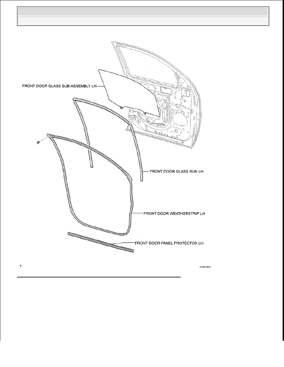
Fig. 98: Identifying Front Door Components (5 Of 5) (For Crewmax) 
Courtesy of TOYOTA MOTOR SALES, U.S.A., INC. 

ON-VEHICLE INSPECTION 

1. INSPECT FRONT DOOR PANEL SUB-ASSEMBLY LH 

a. Check that the clearance measurements of areas A to J are within the standard range. 


2009 Toyota Tundra 

2009 ACCESSORIES AND EQUIPMENT Engine Hood/Door - Tundra


Fig. 99: Identifying Front Door Clearance Between A To J 
Courtesy of TOYOTA MOTOR SALES, U.S.A., INC. 

Standard measurement  

FRONT DOOR PANEL SUB-ASSEMBLY LH STANDARD MEASUREMENT 
SPECIFICATION
 

DISASSEMBLY 

HINT: 

Use the same procedures for the RH side and LH side.  

The procedures listed below are for the LH side.  

1. DISCONNECT CABLE FROM NEGATIVE BATTERY TERMINAL 

Area

Specified Condition

Area

Specified Condition

A

3.7 to 6.7 mm (0.146 to 0.264 in.)

F

0.8 to 3.8 mm (0.0315 to 0.150 in.)

B -1.5 to 1.5 mm (-0.0591 to 0.0591 in.) G

3.7 to 6.7 mm (0.146 to 0.264 in.)

C

3.7 to 6.7 mm (0.146 to 0.264 in.)

H

0.8 to 3.8 mm (0.0315 to 0.150 in.)

D

0.9 to 3.9 mm (0.0354 to 0.154 in.)

I

4.7 to 7.7 mm (0.185 to 0.303 in.)

E

3.7 to 6.7 mm (0.146 to 0.264 in.)

J

-1.5 to 1.5 mm (-0.0591 to 0.0591 in.)


2009 Toyota Tundra 

2009 ACCESSORIES AND EQUIPMENT Engine Hood/Door - Tundra


2. REMOVE FRONT DOOR INSIDE HANDLE BEZEL PLUG LH 

a. Using a screwdriver, detach the 4 claws and remove the inside handle bezel. 

Fig. 100: Identifying Inside Handle Bezel Plug Claws 
Courtesy of TOYOTA MOTOR SALES, U.S.A., INC. 

HINT: 

Tape the screwdriver tip before use. 

3. REMOVE FRONT UPPER ARMREST BASE PANEL LH 

a. Using a screwdriver, detach the 2 clips and front upper armrest base panel. 

Fig. 101: Identifying Front Upper Armrest Base Panel Clips 

CAUTION: Wait at least 90 seconds after disconnecting the cable from the 

negative (-) battery terminal to prevent airbag and seat belt 
pretensioner activation.

NOTE:

Some systems need to be initialized after the cable is reconnected 
(see INITIALIZATION ).  

After the ignition switch is turned OFF, the navigation system 
requires approximately 90 seconds to record various types of 
memory and settings. As a result, after turning the ignition switch 
OFF, wait 90 seconds or more before disconnecting the cable from 
the negative (-) battery terminal.  


2009 Toyota Tundra 

2009 ACCESSORIES AND EQUIPMENT Engine Hood/Door - Tundra


Courtesy of TOYOTA MOTOR SALES, U.S.A., INC. 

HINT: 

Tape the screwdriver tip before use. 

b. Disconnect the connectors.  

4. REMOVE POWER WINDOW REGULATOR MASTER SWITCH ASSEMBLY 

a. Remove the 3 screws and power window regulator master switch. 

Fig. 102: Identifying Screws On Power Window Regulator Master Switch 
Courtesy of TOYOTA MOTOR SALES, U.S.A., INC. 

5. REMOVE FRONT LOWER DOOR FRAME BRACKET GARNISH LH 

a. Detach the 3 clips and remove the front lower door frame bracket garnish.  

Fig. 103: Identifying Front Lower Door Frame Bracket Garnish Clips 


2009 Toyota Tundra 

2009 ACCESSORIES AND EQUIPMENT Engine Hood/Door - Tundra


Content   ..  785  786  787  788   ..