Toyota Tundra. Manual - part 758
 

  Index      Toyota     Toyota Tundra (2007-2010 year) - Service and Repair Manual


Search            copyright infringement  


Content   ..  756  757  758  759   ..


Toyota Tundra. Manual - part 758


TERMINALS OF ECU 

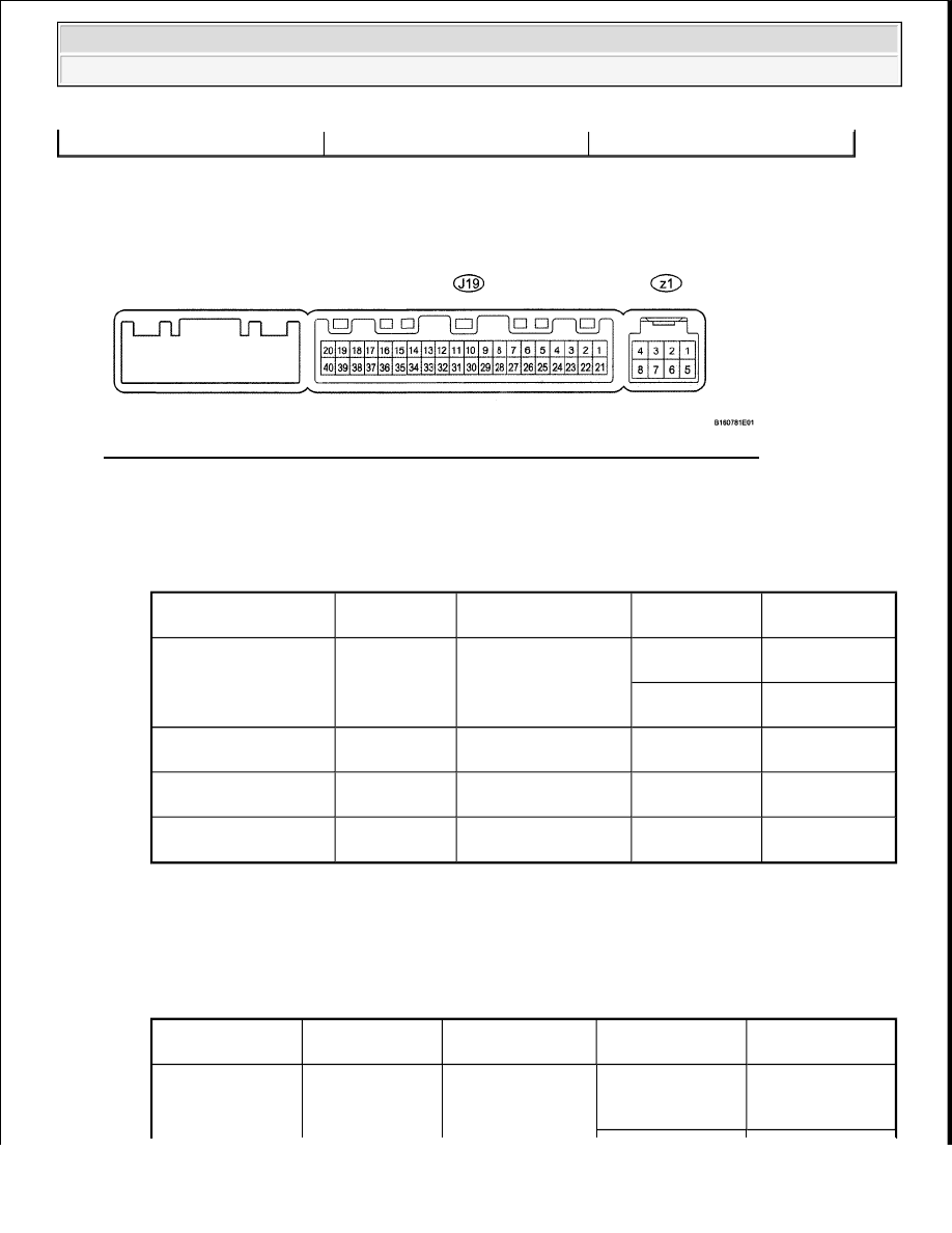
1. CHECK AIR CONDITIONING AMPLIFIER 

Fig. 182: Identifying J19 And z1 Air Conditioning Amplifier Connector Terminals 
Courtesy of TOYOTA MOTOR SALES, U.S.A., INC. 

a. Disconnect the J19 air conditioning amplifier connector.  

b. Measure the resistance and voltage according to the value(s) in the table below. 

AIR CONDITIONING AMPLIFIER RESISTANCE AND VOLTAGE 

If the result is not as specified, there may be a malfunction on the wire harness side. 

c. Reconnect the J19 air conditioning amplifier connector.  

d. Measure the voltage according to the value(s) in the table below. 

AIR CONDITIONING AMPLIFIER VOLTAGE 

Wire harness

-

Terminal No. 

(Symbols)

Wiring Color Terminal Description

Condition

Specified 

Condition

J19-1 (IG+) - J19-14 

(GND)

P-W-B

Ignition power supply

Ignition switch 
ON

11 to 14 V

Ignition switch 

OFF

Below 1 V

J19-21 (B) - J19-14 

(GND)

R-W-B

Battery power source Always

11 to 14 V

J19-37 (LIN1) - J19-14 

(GND)

SB - W-B

LIN communication 
signal

Ignition switch 
ON

Pulse generation

J19-14 (GND) - Body 

ground

W-B - Body 

ground

Ground

Always

Below 1 ohms

Terminal No. 

(Symbols)

Wiring Color

Terminal 

Description

Condition

Specified 

Condition

J19-40 (D) - J19-

Ignition switch ON 
Defogger switch 
OFF

11 to 14 V


2009 Toyota Tundra 

2009 ACCESSORIES AND EQUIPMENT Windshield/WindowGlass - Tundra


If the result is not as specified, the air conditioning amplifier or fuse may have a malfunction. 

2. CHECK INTEGRATION CONTROL AND PANEL 

Fig. 183: Identifying J37 Integration Control And Panel Connector Terminals 
Courtesy of TOYOTA MOTOR SALES, U.S.A., INC. 

a. Disconnect the J37 integration control and panel connector.  

b. Measure the resistance and voltage according to the value(s) in the table below. 

INTEGRATION CONTROL AND PANEL RESISTANCE AND VOLTAGE 

If the result is not as specified, there may be a malfunction on the wire harness side. 

DATA LIST / ACTIVE TEST 

1. ACTIVE TEST 

HINT: 

Using the Techstream to perform Active Tests allows relays, VSVs, actuators and other items to be 
operated without removing any parts. This non-intrusive functional inspection can be very useful because 
intermittent operation may be discovered before parts or wiring is disturbed. Performing Active Tests 

14 (GND)

GR-W-B

Defogger relay

Ignition switch ON 
Defogger switch 
ON

Below 1 V

Terminal No. 

(Symbols)

Wiring Color Terminal Description

Condition

Specified 

Condition

J37-16 (IG+) - J37-1 

(GND)

P-W-B

Ignition power supply

Ignition switch 
OFF

Below 1 V

Ignition switch 

ON

11 to 14 V

J37-3 (STX) - J37-1 

(GND)

SB - W-B

LIN communication 
circuit

Ignition switch 
ON

Pulse generation

J37-1 (GND) - Body 

ground

W-B - Body 

ground

Ground

Always

Below 1 ohms


2009 Toyota Tundra 

2009 ACCESSORIES AND EQUIPMENT Windshield/WindowGlass - Tundra


early in troubleshooting is one way to save diagnostic time. Data List information can be displayed while 
performing Active Tests. 

a. Connect the Techstream to the DLC3.  

b. Turn the ignition switch ON.  

c. Turn the Techstream on.  

d. Enter the following menus: Body / Air Conditioner / Active Test.  

e. According to the display on the Techstream, perform the "Active Test". 

Air Conditioner  

AIR CONDITIONER - TECHSTREAM TESTER DISPLAY REFERENCE CHART 

WINDSHIELD DEICER DOES NOT OPERATE 

DESCRIPTION 

When the windshield deicer switch turns is turned ON, a windshield deicer activation request signal is sent via 
the LIN communication line to the air conditioning amplifier. Then the air conditioning amplifier operates the 
windshield deicer. 

WIRING DIAGRAM 

Tester Display

Test Part

Control Range Diagnostic Note

Deicer Relay (Front) Deicer relay operation

OFF or ON

-


2009 Toyota Tundra 

2009 ACCESSORIES AND EQUIPMENT Windshield/WindowGlass - Tundra


Fig. 184: Windshield Deicer Does Not Operate Wiring Diagram 
Courtesy of TOYOTA MOTOR SALES, U.S.A., INC. 

INSPECTION PROCEDURE 

HINT: 

This circuit uses the LIN communication line. Before performing the inspection, check that the LIN 
communication system is functioning normally (see HOW TO PROCEED WITH TROUBLESHOOTING ). 

1. PERFORM ACTIVE TEST BY TECHSTREAM (DEICER RELAY) 

a. Select the Active Test using the Techstream to generate a control command, and then check that the 

windshield deicer operates. 

Air Conditioner  

AIR CONDITIONER - TECHSTREAM TESTER DISPLAY REFERENCE CHART 

OK: Deicer relay turns ON and OFF.  

NG: Go to step 3 

OK: Go to Next Step  

2. CHECK INTEGRATION CONTROL AND PANEL (OPERATION) 

a. Temporarily replace the integration control and panel with a new or normally functioning one. 

1. For Column Shift Type, refer to the following procedures (see INTEGRATION 

CONTROL AND PANEL (FOR COLUMN SHIFT TYPE) ).  

2. For Floor Shift Type, refer to the following procedures (see INTEGRATION CONTROL 

AND PANEL (FOR FLOOR SHIFT TYPE) ).  

b. Check that the malfunction disappears. 

OK: Malfunction disappears.  

NG: REPLACE AIR CONDITIONING AMPLIFIER (See AIR CONDITIONING AMPLIFIER ) 

OK: END (INTEGRATION CONTROL AND PANEL IS DEFECTIVE)  

3. INSPECT FUSE (DEICER) 

a. Remove the DEICER fuse from the engine room relay block.  

b. Measure the resistance according to the value(s) in the table below. 

Standard resistance  

Tester Display

Test Part

Control Range Diagnostic Note

Deicer Relay (Front) Deicer relay operation

OFF or ON

-


2009 Toyota Tundra 

2009 ACCESSORIES AND EQUIPMENT Windshield/WindowGlass - Tundra


Content   ..  756  757  758  759   ..