Toyota Tundra. Manual - part 617


  Index      Toyota     Toyota Tundra (2007-2010 year) - Service and Repair Manual


Search            copyright infringement  


Content   ..  615  616  617  618   ..


Toyota Tundra. Manual - part 617


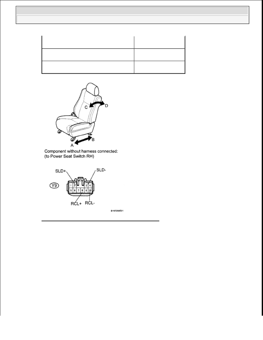
Fig. 22: Inspecting Front Seat Adjuster Assembly RH 
Courtesy of TOYOTA MOTOR SALES, U.S.A., INC. 

NG: Go to step 17  

OK: REPAIR OR REPLACE HARNESS OR CONNECTOR (FRONT POWER SEAT SWITCH 
RH-BATTERY AND BODY GROUND)
  

17. CHECK HARNESS AND CONNECTOR (FRONT POWER SEAT SWITCH RH - POSITION 

MOTOR) 

a. Disconnect the Y9 switch connector.  

b. Disconnect the Y12 and Y13 motor connectors.  

c. Measure the resistance according to the value(s) in the table below. 

Standard resistance  

Battery negative (-) --> Terminal 2 (SLD+) 

Battery positive (+) --> Terminal 3 (SLD-)

Seat slides rearward (B)

Battery positive (+) --> Terminal 8 (RCL+) 

Battery negative (-) --> Terminal 10 (RCL-)

Seat tilts forward (C)

Battery negative (-) --> Terminal 8 (RCL+) 

Battery positive (+) --> Terminal 10 (RCL-)

Seat reclines (D)


2009 Toyota Tundra 

2009 ACCESSORIES AND EQUIPMENT Seat - Tundra


FRONT POWER SEAT SWITCH RH - POSITION MOTOR 

Fig. 23: Identifying Front Power Seat Switch And Position Motor Connector Terminals 
Courtesy of TOYOTA MOTOR SALES, U.S.A., INC. 

NG: REPAIR OR REPLACE HARNESS OR CONNECTOR  

OK: REPLACE FRONT SEAT ADJUSTER ASSEMBLY RH (see REMOVAL ) 

Tester Connection

Condition Specified Condition

Y9-2 (SLD+) - Y12-1

Always

Below 1 ohms

Y9-3 (SLD-) - Y12-2

Y9-8 (RCL+) - Y13-2

Y9-10 (RCL-) - Y13-1

Y9-2 (SLD+) - Body ground

Always

10 kohms or higher

Y9-3 (SLD-) - Body ground

Y9-8 (RCL+) - Body ground

Y9-10 (RCL-) - Body ground


2009 Toyota Tundra 

2009 ACCESSORIES AND EQUIPMENT Seat - Tundra


18. INSPECT FUSE (FR P/SEAT RH) 

a. Remove the FR P/SEAT RH fuse from the main body ECU.  

b. Measure the resistance according to the value(s) in the table below. 

Standard resistance  

FUSE (FR P/SEAT RH) 

NG: REPLACE FUSE  

OK: Go to next step  

19. INSPECT FRONT POWER SEAT LUMBAR SWITCH 

a. Remove the switch (see REMOVAL ).  

b. Measure the resistance according to the value(s) in the table below. 

Standard resistance  

FRONT POWER SEAT LUMBAR SWITCH 

Tester Connection Condition Specified Condition

FR P/SEAT RH fuse Always

Below 1 ohms

Tester Connection Switch Condition Specified Condition

3 (B) - 4 (H)

HOLD

Below 1 ohms

1 (R) - 2 (E2)
1 (R) - 2 (E2) 

4 (H) - 5 (E)

OFF

1 (R) - 3 (B)

RELEASE

4 (H) - 5 (E)


2009 Toyota Tundra 

2009 ACCESSORIES AND EQUIPMENT Seat - Tundra


Fig. 24: Identifying Front Power Seat Lumbar Switch Connector Terminals 
Courtesy of TOYOTA MOTOR SALES, U.S.A., INC. 

NG: REPLACE FRONT POWER SEAT LUMBAR SWITCH (see REMOVAL ) 

OK: Go to next step  

20. INSPECT FRONT SEAT ADJUSTER ASSEMBLY RH 

a. Disconnect the Y10 switch connector.  

b. Apply battery voltage and check the operation of the power seat. 

OK  

FRONT SEAT ADJUSTER ASSEMBLY RH 

Measurement Condition

Specified Condition

Battery positive (+) --> Terminal Y10-4 (H) 

Battery negative (-) --> Terminal Y10-1 (R)

Lumbar support moves forward (A)

Battery negative (-) --> Terminal Y10-4 (H) 
Battery positive (+) --> Terminal Y10-1 (R)

Lumbar support moves rearward (B)


2009 Toyota Tundra 

2009 ACCESSORIES AND EQUIPMENT Seat - Tundra


Content   ..  615  616  617  618   ..