Toyota Tundra. Manual - part 580
CHART
If the power source circuit is operating normally, proceed to the next step.
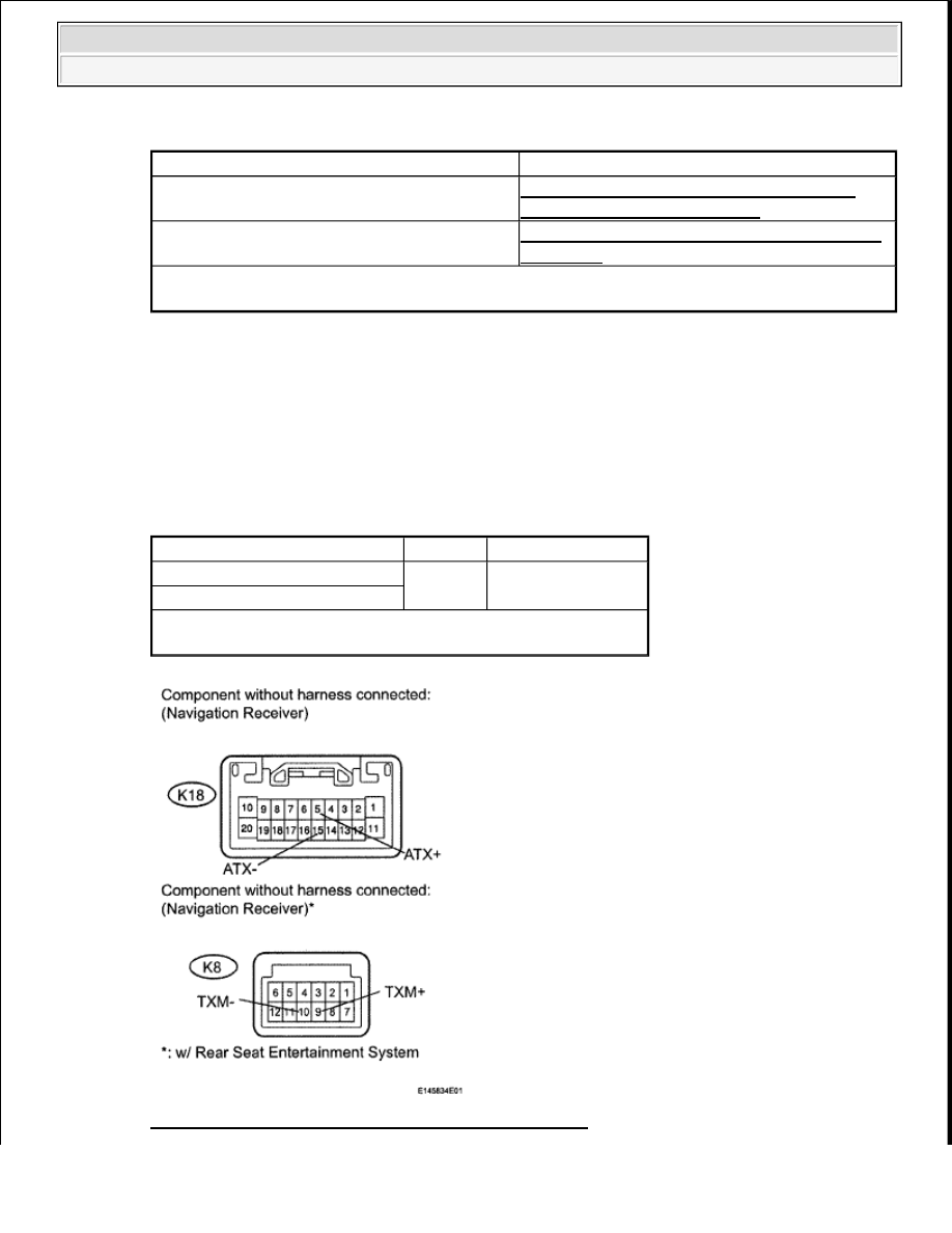
3. INSPECT NAVIGATION RECEIVER
a. Disconnect the K18 and K8 receiver connectors.
b. Measure the resistance according to the value(s) in the table below.
Standard resistance
NAVIGATION RECEIVER TESTER CONNECTION SPECIFIED CONDITION
Fig. 436: Identifying K18 And K8 Receiver Connectors
Component
Proceed to
Navigation receiver (140)
NAVIGATION RECEIVER ASSEMBLY
POWER SOURCE CIRCUIT
Television display (1B0)*
TELEVISION DISPLAY POWER SOURCE
CIRCUIT *
HINT:
*: w/ Rear Seat Entertainment System
Tester Connection
Condition Specified Condition
K18-5 (ATX+) - K18-15 (ATX-)
Always
60 to 80 ohms
K8-9 (TXM+) - K8-10 (TXM-)*
HINT:
*: w/ Rear Seat Entertainment System
2009 Toyota Tundra
2009 ACCESSORIES AND EQUIPMENT Navigation - Tundra