Toyota Tundra. Manual - part 430
 

  Index      Toyota     Toyota Tundra (2007-2010 year) - Service and Repair Manual


Search            copyright infringement  


Content   ..  428  429  430  431   ..


Toyota Tundra. Manual - part 430


HARNESS AND CONNECTOR (ACCESSORY METER - BATTERY AND BODY 
GROUND) RESISTANCE REFERENCE
 

NG: REPAIR OR REPLACE HARNESS OR CONNECTOR  

OK: Go to next step  

4. REPLACE ACCESSORY METER ASSEMBLY 

a. Temporarily replace the accessory meter with a new or normally functioning one (see ON-

VEHICLE INSPECTION ).  

5. CHECK ACCESSORY METER ASSEMBLY (OPERATION) 

a. Check that the accessory meter operation is normal. 

OK: Operation of accessory meter returns to normal.  

NG: REPLACE COMBINATION METER ASSEMBLY (see REMOVAL ) 

OK: END (ACCESSORY METER IS DEFECTIVE)  

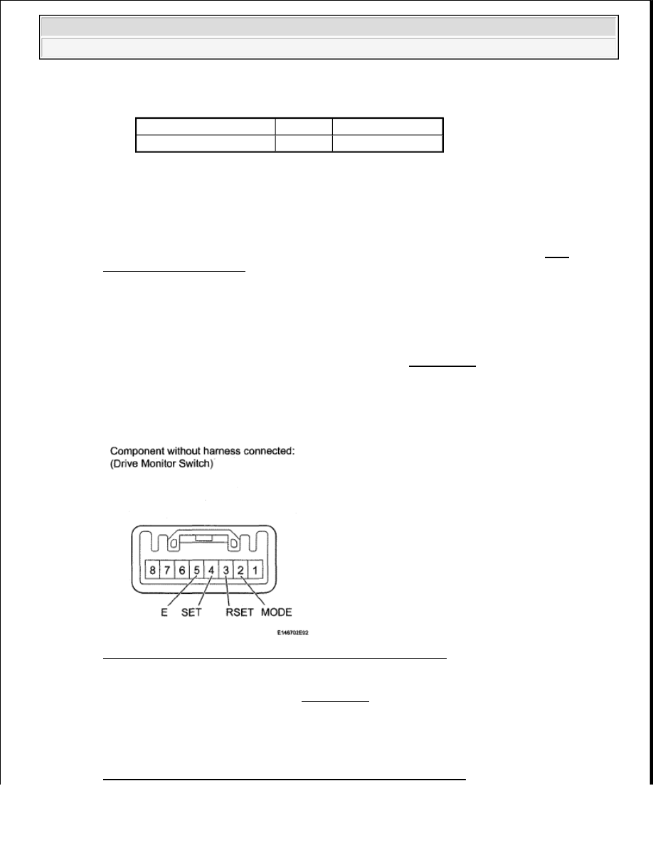
6. INSPECT DRIVE MONITOR SWITCH 

Fig. 50: Identifying Drive Monitor Switch Connector Terminal 
Courtesy of TOYOTA MOTOR SALES, U.S.A., INC. 

a. Remove the drive monitor switch (see REMOVAL ).  

b. Measure the resistance according to the value(s) in the table below. 

Standard resistance  

DRIVE MONITOR SWITCH RESISTANCE REFERENCE 

Tester Connection

Condition Specified Condition

K20-12 (E) - Body ground Always

Below 1 ohms


2009 Toyota Tundra 

2009 ACCESSORIES AND EQUIPMENT Meter - Tundra


NG: REPLACE DRIVE MONITOR SWITCH (see REMOVAL ) 

OK: Go to next step  

7. CHECK HARNESS AND CONNECTOR (COMBINATION METER - DRIVE MONITOR 

SWITCH AND BODY GROUND) 

a. Disconnect the J28 combination meter connector. 

Fig. 51: Identifying L2 Drive Monitor Switch Connector Terminal J28 Combination Meter 
Connector Terminal
 
Courtesy of TOYOTA MOTOR SALES, U.S.A., INC. 

b. Disconnect the L2 drive monitor switch connector.  

c. Measure the resistance according to the value(s) in the table below. 

Standard resistance  

Tester Connection

Switch Condition

Specified Condition

2 (MODE) - 5 (E)

INFO switch pressed

Below 1 ohms

INFO switch not pressed

10 kohms or higher

4 (SET)-5 (E)

SETUP switch pressed

Below 1 ohms

SETUP switch not pressed 10 kohms or higher

3 (RSET) - 5 (E)

SELECT switch pressed

Below 1 ohms

SELECT switch not pressed 10 kohms or higher


2009 Toyota Tundra 

2009 ACCESSORIES AND EQUIPMENT Meter - Tundra


HARNESS AND CONNECTOR (COMBINATION METER - DRIVE MONITOR SWITCH 
AND BODY GROUND) RESISTANCE REFERENCE
 

NG: REPAIR OR REPLACE HARNESS OR CONNECTOR  

OK: Go to next step  

8. CHECK HARNESS AND CONNECTOR (COMBINATION METER - ACCESSORY METER) 

a. Disconnect the J28 combination meter connector. 

Fig. 52: Identifying J28 Combination Meter Connector Terminal K20 Accessory Meter 
Connector Terminal
 
Courtesy of TOYOTA MOTOR SALES, U.S.A., INC. 

b. Disconnect the K20 accessory meter connector.  

c. Measure the resistance according to the value(s) in the table below. 

Tester Connection

Condition Specified Condition

J28-28 (A/B) - L2-2 (INFO)

Always

Below 1 ohms

J28-29 (E) - L2-4 (SET)

J28-30 (RSET) - L2-3 (RSET)

L2-5 (E) - Body ground

J28-28 (A/B) - Body ground

Always

10 kohms or higher

J28-29 (E) - Body ground

J28-30 (RSET) - Body ground


2009 Toyota Tundra 

2009 ACCESSORIES AND EQUIPMENT Meter - Tundra


Standard resistance  

HARNESS AND CONNECTOR (COMBINATION METER - ACCESSORY METER) 
RESISTANCE REFERENCE
 

NG: REPAIR OR REPLACE HARNESS OR CONNECTOR  

OK: Go to next step  

9. REPLACE ACCESSORY METER ASSEMBLY 

a. Temporarily replace the accessory meter with a new or normally functioning one (see ON-

VEHICLE INSPECTION ).  

10. CHECK ACCESSORY METER ASSEMBLY (OPERATION) 

a. Check that the accessory meter operation is normal. 

OK: Operation of accessory meter returns to normal.  

NG: REPLACE COMBINATION METER ASSEMBLY (see REMOVAL ) 

OK: END (ACCESSORY METER IS DEFECTIVE)  

OIL PRESSURE RECEIVER GAUGE MALFUNCTION 

DESCRIPTION 

The oil pressure sender detects the oil pressure generated when the engine is started. The combination meter 
determines that the engine is running when the engine speed is 400 rpm or more, and determines that the engine 
is cranking when the engine speed is 200 rpm or less. The oil pressure receiver gauge detects and indicates the 
oil pressure applied to the oil pressure sender. 

WIRING DIAGRAM 

Tester Connection

Condition Specified Condition

J28-31 (TX+) - K20-10 (TX-) Always

Below 1 ohms

J28-31 (TX+) - Body ground

Always

10 kohms or higher


2009 Toyota Tundra 

2009 ACCESSORIES AND EQUIPMENT Meter - Tundra


Content   ..  428  429  430  431   ..