Toyota Tundra. Manual - part 2862


  Index      Toyota     Toyota Tundra (2007-2010 year) - Service and Repair Manual


Search            copyright infringement  


Content   ..  2860  2861  2862  2863   ..


Toyota Tundra. Manual - part 2862


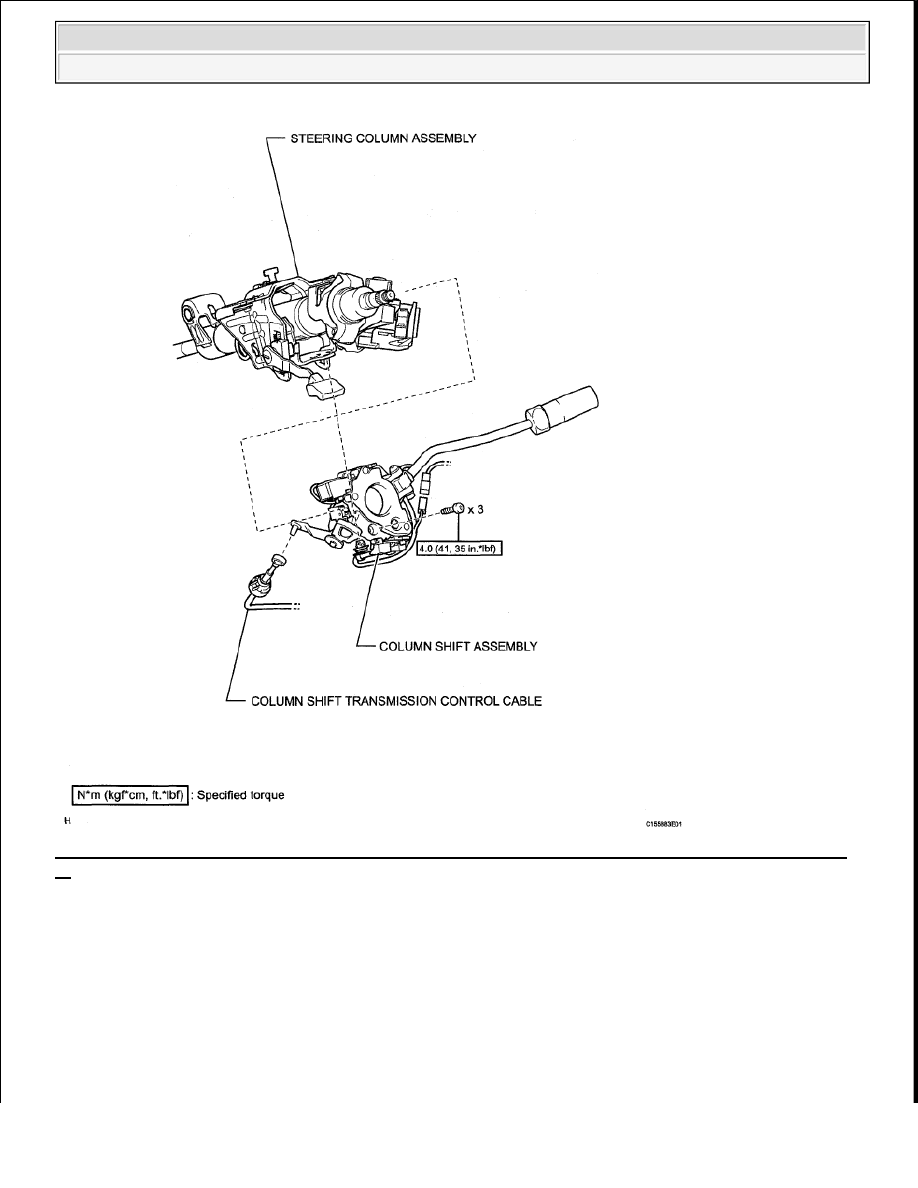
Fig. 229: Identifying Shift Lever Assembly Replacement Components With Torque Specifications (2 Of 
3)
 
Courtesy of TOYOTA MOTOR SALES, U.S.A., INC. 


2009 Toyota Tundra 

2009 TRANSMISSION AB60F Automatic Transaxle - Tundra


Fig. 230: Identifying Shift Lever Assembly Replacement Components With Torque Specifications (3 Of 
3)
 
Courtesy of TOYOTA MOTOR SALES, U.S.A., INC. 

ON-VEHICLE INSPECTION 


2009 Toyota Tundra 

2009 TRANSMISSION AB60F Automatic Transaxle - Tundra


1. INSPECT SHIFT LEVER POSITION 

a. When moving the shift lever from the P to R position with the ignition switch ON and brake pedal 

depressed, make sure that it moves smoothly and correctly into position.  

b. Start the engine and make sure that the vehicle moves forward after moving the shift lever from the 

N to D position, and moves rearward after moving the shift lever to the R position. 

If the operation cannot be performed as specified, inspect the park/neutral position switch assembly 
and check the shift lever assembly installation condition. 

REMOVAL 

1. DISCONNECT CABLE FROM NEGATIVE BATTERY TERMINAL 

2. REMOVE FRONT DOOR SCUFF PLATE LH (for Regular Cab) (See REMOVAL )  

3. REMOVE FRONT DOOR SCUFF PLATE LH (for Double Cab, CrewMax) (See REMOVAL and 

REMOVAL )  

4. REMOVE COWL SIDE TRIM BOARD LH (See REMOVAL )  

5. REMOVE LOWER INSTRUMENT PANEL FINISH PANEL SUB-ASSEMBLY LH (See 

REMOVAL )  

6. REMOVE NO. 1 INSTRUMENT PANEL SAFETY PAD INSERT (See REMOVAL )  

7. REMOVE STEERING PAD (w/o Steering Pad Switch) (See REMOVAL )  

8. REMOVE STEERING PAD (w/Steering Pad Switch) (See REMOVAL )  

9. REMOVE STEERING WHEEL ASSEMBLY (See REMOVAL )  

10. REMOVE LOWER STEERING COLUMN COVER (See REMOVAL )  

11. REMOVE UPPER STEERING COLUMN COVER (See REMOVAL )  

12. REMOVE TURN SIGNAL SWITCH ASSEMBLY WITH SPIRAL CABLE SUB-ASSEMBLY 

(See REMOVAL )  

13. REMOVE COLUMN SHIFT ASSEMBLY 

a. Move the shift lever to the N position.  

b. Disconnect the column shift transmission control cable end from the column shift. 

CAUTION: Wait at least 90 seconds after disconnecting the cable from the 

negative (-) battery terminal to prevent airbag and seat belt 
pretensioner activation.

NOTE:

Some systems need to be initialized after the cable is reconnected 
(see INITIALIZATION ).  

After the ignition switch is turned OFF, the navigation system 
requires approximately 90 seconds to record various types of 
memory and settings. As a result, after turning the ignition switch 
OFF, wait 90 seconds or more before disconnecting the cable from 
the negative (-) battery terminal.  


2009 Toyota Tundra 

2009 TRANSMISSION AB60F Automatic Transaxle - Tundra


Fig. 231: Identifying Column Shift 
Courtesy of TOYOTA MOTOR SALES, U.S.A., INC. 

c. Disconnect the connector and detach the harness clamp.  

d. Using a T30 "TORX" wrench, remove the 3 bolts and column shift. 

Fig. 232: Locating Column Shift Bolts 
Courtesy of TOYOTA MOTOR SALES, U.S.A., INC. 

DISASSEMBLY 

1. REMOVE COLUMN SHIFT SHIFTING BELLCRANK ASSEMBLY 

a. Remove the bolt and shifting bellcrank from the column shift control shift lever retainer. 


2009 Toyota Tundra 

2009 TRANSMISSION AB60F Automatic Transaxle - Tundra


Content   ..  2860  2861  2862  2863   ..