Content .. 2716 2717 2718 2719 ..
Toyota Tundra. Manual - part 2718
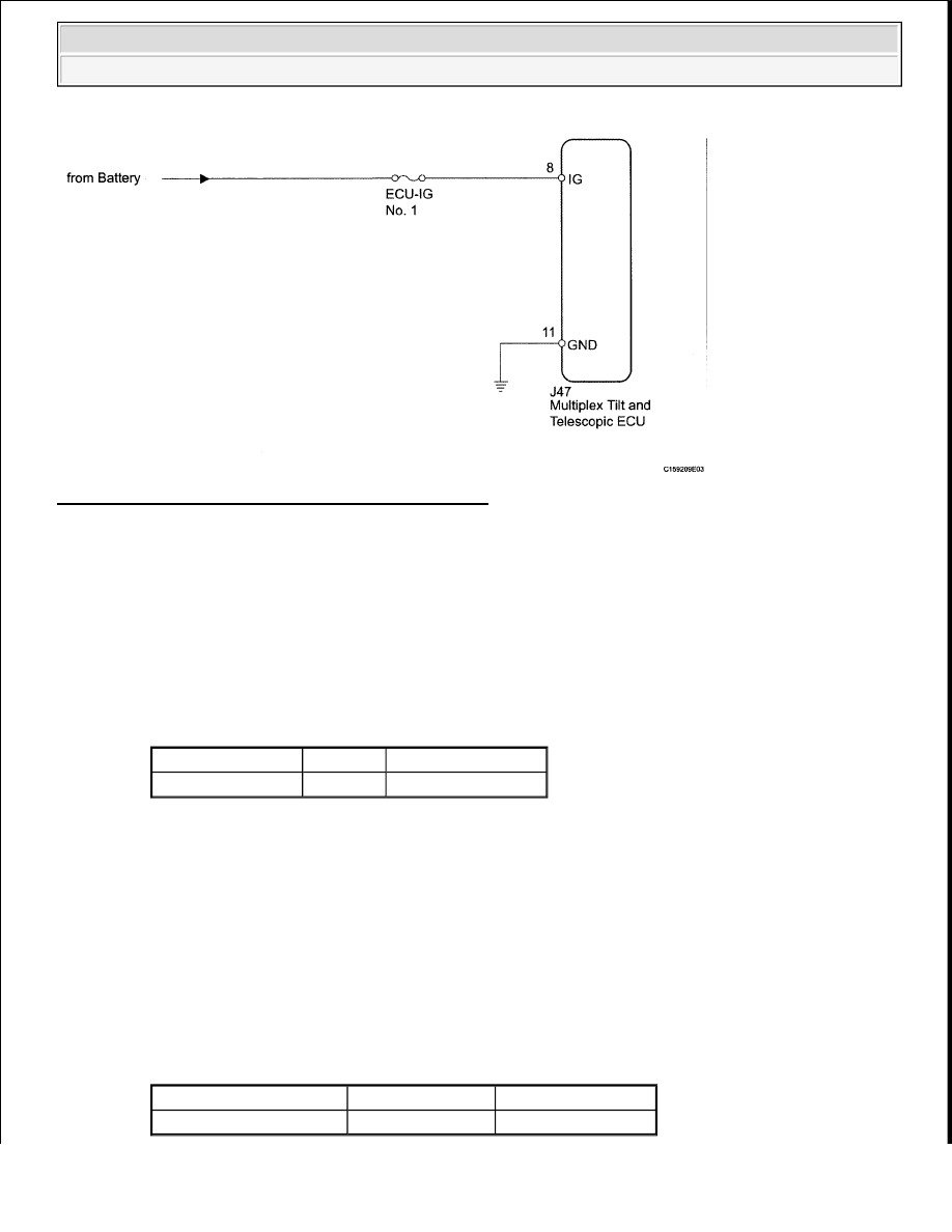
Fig. 43: Identifying IG Power Source Wiring Diagram
Courtesy of TOYOTA MOTOR SALES, U.S.A., INC.
INSPECTION PROCEDURE
1. INSPECT FUSE (ECU-IG No. 1)
a. Remove the ECU-IG No. 1 fuse from the main body ECU.
b. Measure the resistance according to the value (s) in the table below.
Standard Resistance
STANDARD RESISTANCE SPECIFICATION TABLE
NG: REPLACE FUSE
OK: Go to next step.
2. CHECK HARNESS AND CONNECTOR (MULTIPLEX TILT AND TELESCOPIC ECU -
BATTERY)
a. Disconnect the J47 multiplex tilt and telescopic ECU connector.
b. Measure the voltage according to the value (s) in the table below.
Standard Voltage
STANDARD VOLTAGE SPECIFICATION TABLE
Tester Connection Condition Specified Condition
ECU-IG No. 1 fuse Always
Below 1 ohms
Tester Connection
Switch Condition Specified Condition
J47-8 (IG) - Body ground Ignition switch ON
11 to 14 V
2009 Toyota Tundra
2009 STEERING Steering Column - Tundra