Toyota Tundra. Manual - part 2422


  Index      Toyota     Toyota Tundra (2007-2010 year) - Service and Repair Manual


Search            copyright infringement  


Content   ..  2420  2421  2422  2423   ..


Toyota Tundra. Manual - part 2422


1. CHECK FOR DTC (CAN COMMUNICATION SYSTEM) 

a. Use the Techstream to check if the CAN communication system is functioning normally. 

Result  

RESULT REFERENCE 

B: GO TO CAN COMMUNICATION SYSTEM (See PRECAUTION )  

A: Go to Next Step  

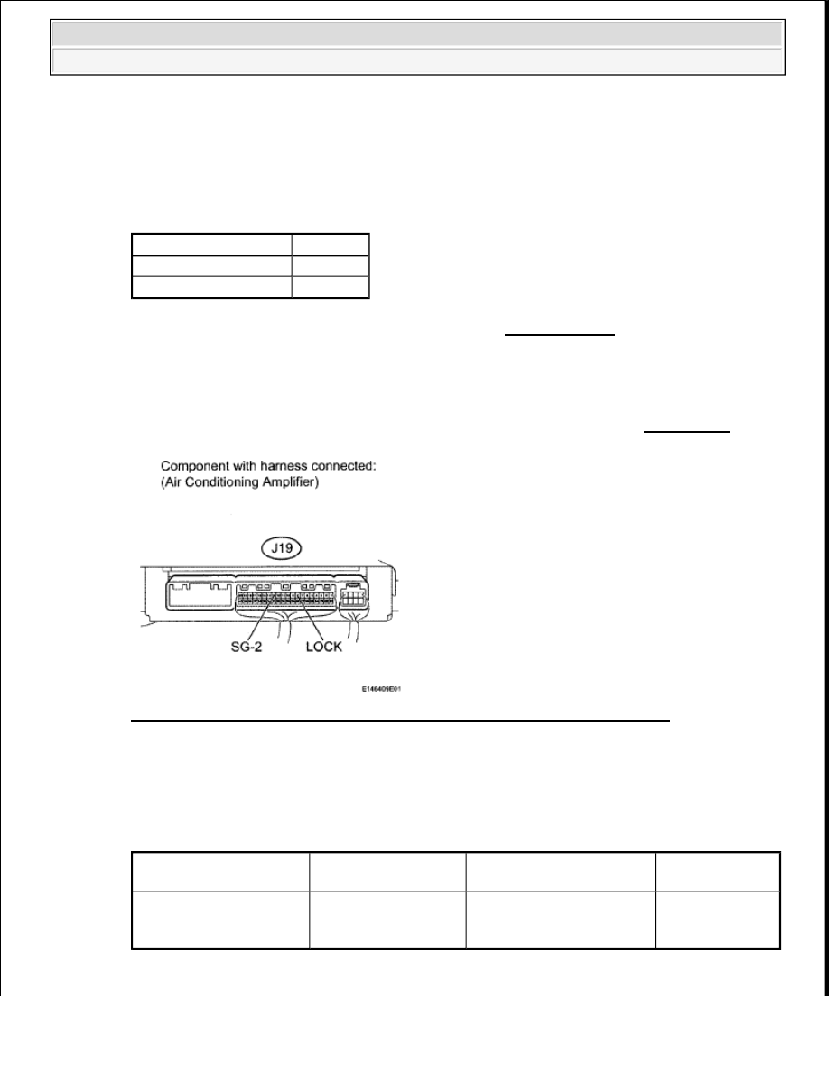
2. CHECK AIR CONDITIONING AMPLIFIER 

a. Remove the air conditioning amplifier with the connectors still connected (see REMOVAL ). 

Fig. 113: Identifying Terminals Of J19 Air Conditioning Amplifier Connector 
Courtesy of TOYOTA MOTOR SALES, U.S.A., INC. 

b. Using an oscilloscope, check the waveform. 

Standard  

TESTER CONNECTION SPECIFIED CONDITION CHART 

Result  

Result

Proceed to

CAN DTC is not output

A

CAN DTC is output

B

Tester Connection

Tool Setting

Condition

Specified 

Condition

J19-8 (LOCK) - J19-13 

(SG-2)

200 mV/DIV., 10 
ms./DIV.

Engine is running A/C 
switch ON 
Blower switch LO

Pulse generation


2009 Toyota Tundra 

2009 HVAC Air Conditioning - Tundra


RESULT REFERENCE 

Fig. 114: Identifying Waveform 
Courtesy of TOYOTA MOTOR SALES, U.S.A., INC. 

B: PROCEED TO NEXT CIRCUIT INSPECTION SHOWN IN PROBLEM SYMPTOMS 
TABLE
 (See PROBLEM SYMPTOMS TABLE ) 

C: REPLACE AIR CONDITIONING AMPLIFIER (See REMOVAL ) 

A: Go to Next Step  

3. INSPECT AIR CONDITIONING COMPRESSOR (LOCK SENSOR) 

a. Disconnect the connector from the air conditioning compressor. 

Fig. 115: Identifying Terminals Of Air Conditioning Compressor Connector 
Courtesy of TOYOTA MOTOR SALES, U.S.A., INC. 

Result

Proceed to

NG

A

OK (Checking from the PROBLEM SYMPTOMS TABLE)

B

OK (Checking from the DTC)

C


2009 Toyota Tundra 

2009 HVAC Air Conditioning - Tundra


b. Measure the resistance, according to the value(s) in the table below. 

Standard Resistance  

for 1GR-FE  

TESTER CONNECTION SPECIFIED CONDITION CHART 

for 2UZ-FE, 3UR-FE  

TESTER CONNECTION SPECIFIED CONDITION CHART 

Result  

RESULT REFERENCE 

B: REPLACE AIR CONDITIONING COMPRESSOR (LOCK SENSOR) (See REMOVAL ) 

C: REPLACE AIR CONDITIONING COMPRESSOR (LOCK SENSOR) (See REMOVAL ) 

D: REPLACE AIR CONDITIONING COMPRESSOR (LOCK SENSOR) (See REMOVAL ) 

A: Go to Next Step  

4. CHECK HARNESS AND CONNECTOR (AIR CONDITIONING AMPLIFIER - AIR 

CONDITIONING COMPRESSOR) 

a. Disconnect the J19 air conditioning amplifier connector.  

b. Disconnect the D60 air conditioning compressor connector. 

Tester Connection Condition Specified Condition

1 (SSR+) - 2 (SSR-) 20°C (68°F)

165 to 205 ohms

Tester Connection Condition Specified Condition

1 (SSR+) - 2 (SSR-) 20°C (68°F)

65 to 125 ohms

Result

Proceed to

OK

A

NG (for 1GR-FE)

B

NG (for 2UZ-FE)

C

NG (for 3UR-FE or 3UR-FBE)

D


2009 Toyota Tundra 

2009 HVAC Air Conditioning - Tundra


Fig. 116: Identifying Terminals Of D60 Air Conditioning Compressor Connector 
Courtesy of TOYOTA MOTOR SALES, U.S.A., INC. 

c. Measure the resistance according to the value(s) in the table below. 

Standard Resistance  

TESTER CONNECTION SPECIFIED CONDITION CHART 

NG: REPAIR OR REPLACE HARNESS OR CONNECTOR  

OK: REPLACE AIR CONDITIONING AMPLIFIER (See REMOVAL ) 

DTC B1423/23 PRESSURE SENSOR CIRCUIT 

DESCRIPTION 

Tester Connection

Condition Specified Condition

J19-8 (LOCK) - D60-1 (SSR+)

Always

Below 1 ohms

J19-13 (SG-2) - D60-2 (SSR-)

J19-8 (LOCK) or D60-1 (SSR+) - Body ground

Always

10 kohms or higher

J19-13 (SG-2) or D60-2 (SSR-) - Body ground


2009 Toyota Tundra 

2009 HVAC Air Conditioning - Tundra


Content   ..  2420  2421  2422  2423   ..