Toyota Tundra. Manual - part 2420


  Index      Toyota     Toyota Tundra (2007-2010 year) - Service and Repair Manual


Search            copyright infringement  


Content   ..  2418  2419  2420  2421   ..


Toyota Tundra. Manual - part 2420


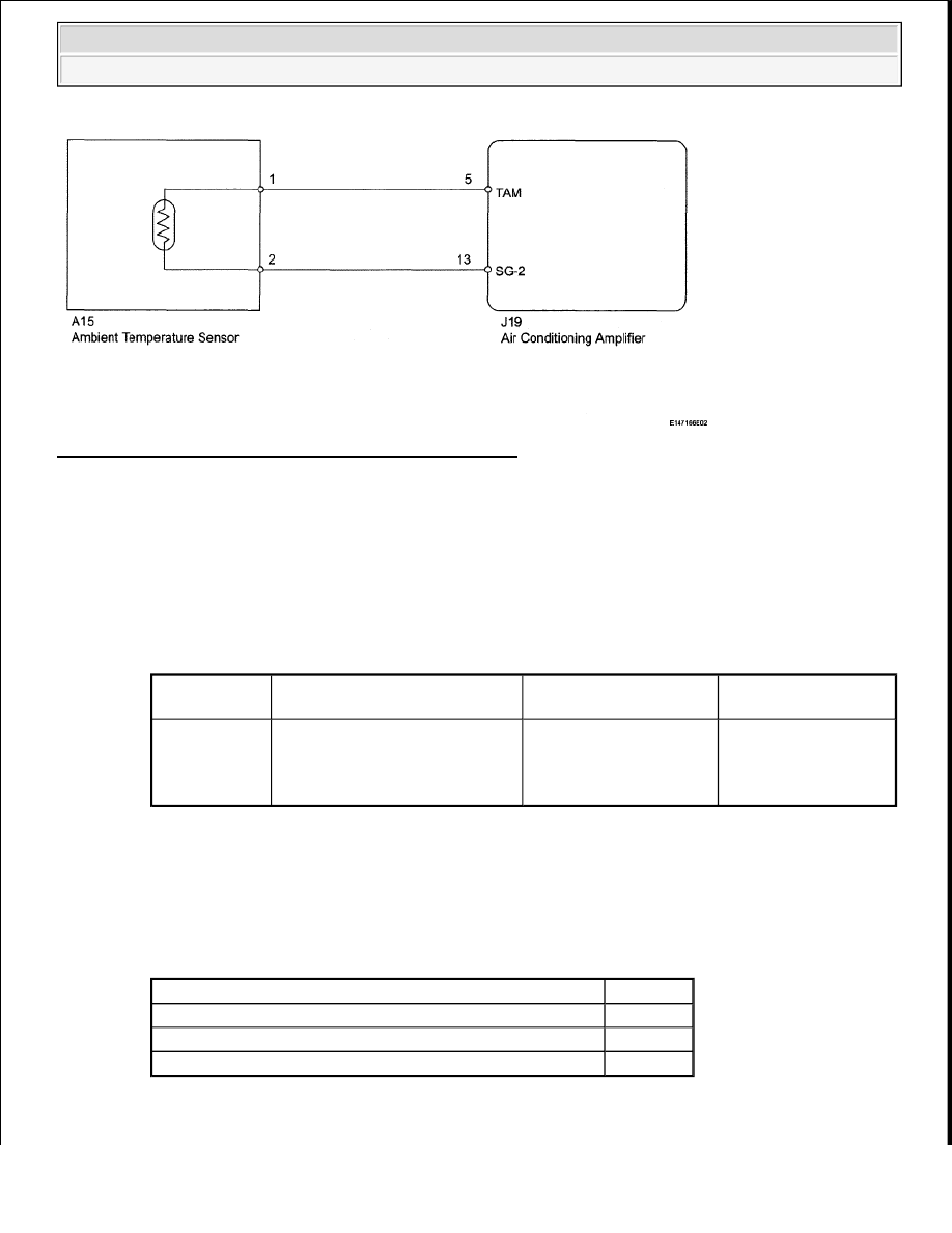
Fig. 107: Ambient Temperature Sensor - Wiring Diagram 
Courtesy of TOYOTA MOTOR SALES, U.S.A., INC. 

INSPECTION PROCEDURE 

1. READ VALUE USING TECHSTREAM (AMBIENT TEMPERATURE SENSOR) 

a. Use the Data List to check if the ambient temperature sensor is functioning properly. 

Air Conditioner  

DATA LIST 

OK:  

The display is as specified in the normal condition.  

Result  

RESULT REFERENCE 

B: PROCEED TO NEXT CIRCUIT INSPECTION SHOWN IN PROBLEM SYMPTOMS 

Tester 

Display

Measurement Item/Range

Normal Condition

Diagnostic Note

Ambient Temp 

Sensor

Ambient temperature 
sensor/Min.: -23.3°C (-9.94°F) 
Max.: 65.95°C (150.71°F)

Actual ambient 
temperature is displayed

Open in circuit: -23.3°
C (-9.94°F) 
Short in circuit: 65.95°
C (150.71°F)

Result

Proceed to

NG

A

OK (Checking from the PROBLEM SYMPTOMS TABLE)

B

OK (Checking from the DTC)

C


2009 Toyota Tundra 

2009 HVAC Air Conditioning - Tundra


TABLE (See PROBLEM SYMPTOMS TABLE ) 

C: REPLACE AIR CONDITIONING AMPLIFIER (See REMOVAL ) 

A: Go to Next Step  

2. INSPECT AMBIENT TEMPERATURE SENSOR 

a. Remove the ambient temperature sensor (see REMOVAL ). 

Fig. 108: Temperature And Resistance Graph 
Courtesy of TOYOTA MOTOR SALES, U.S.A., INC. 

b. Measure the resistance according to the value(s) in the table below. 

Standard Resistance  


2009 Toyota Tundra 

2009 HVAC Air Conditioning - Tundra


TESTER CONNECTION SPECIFIED CONDITION CHART 

HINT: 

As the temperature increases, the resistance decreases (see the graph ). 

NG: REPLACE AMBIENT TEMPERATURE SENSOR (See REMOVAL ) 

OK: Go to Next Step  

3. CHECK HARNESS AND CONNECTOR (AMBIENT TEMPERATURE SENSOR - AIR 

CONDITIONING AMPLIFIER) 

a. Disconnect the A15 sensor connector.  

b. Disconnect the J19 air conditioning amplifier connector. 

Tester Connection Condition Specified Condition

1 - 2

10°C (50°F) 3.00 to 3.73 kohms
15°C (59°F) 2.45 to 2.88 kohms
20°C (68°F) 1.95 to 2.30 kohms
25°C (77°F) 1.60 to 1.80 kohms
30°C (86°F) 1.28 to 1.47 kohms
35°C (95°F) 1.00 to 1.22 kohms

40°C (104°F) 0.80 to 1.00 kohms
45°C (113°F) 0.65 to 0.85 kohms
50°C (122°F) 0.50 to 0.70 kohms
55°C (131°F) 0.44 to 0.60 kohms
60°C (140°F) 0.36 to 0.50 kohms

NOTE:

Even slightly touching the sensor may change the resistance 
value. Be sure to hold the connector of the sensor.  

When measuring, the sensor temperature must be the same as 
the ambient temperature.  


2009 Toyota Tundra 

2009 HVAC Air Conditioning - Tundra


Fig. 109: Identifying Terminals Of J19 Air Conditioning Amplifier Connector 
Courtesy of TOYOTA MOTOR SALES, U.S.A., INC. 

c. Measure the resistance according to the value(s) in the table below. 

Standard Resistance  

TESTER CONNECTION SPECIFIED CONDITION CHART 

NG: REPAIR OR REPLACE HARNESS OR CONNECTOR  

OK: REPLACE AIR CONDITIONING AMPLIFIER (See REMOVAL ) 

DTC B1413/13 EVAPORATOR TEMPERATURE SENSOR CIRCUIT 

DESCRIPTION 

Tester Connection

Condition Specified Condition

A15-1 - J19-5 (TAM)

Always

Below 1 ohms

A15-2 - J19-13 (SG-2)

A15-1 or J19-5 (TAM) - Body ground

Always

10 kohms or higher

A15-2 or J19-13 (SG-2) - Body ground


2009 Toyota Tundra 

2009 HVAC Air Conditioning - Tundra


Content   ..  2418  2419  2420  2421   ..