Toyota Tundra. Manual - part 1921


  Index      Toyota     Toyota Tundra (2007-2010 year) - Service and Repair Manual


Search            copyright infringement  


Content   ..  1919  1920  1921  1922   ..


Toyota Tundra. Manual - part 1921


Arrange the removed parts in the correct order  

5

REMOVE VALVE STEM CAP 

a

Remove the 16 valve stem caps from the cylinder head  

HINT: 

Arrange the removed parts in the correct order  

6

REMOVE CYLINDER HEAD SUB-ASSEMBLY LH 

a

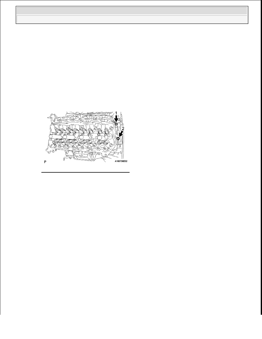
Uniformly loosen and remove the 2 bolts in the sequence shown in the illustration  

Fig. 18: Identifying Cylinder Head Bolts 
Courtesy of TOYOTA MOTOR SALES, U.S.A., INC. 

b

Using a 10 mm bi-hexagon wrench, uniformly loosen the 10 cylinder head bolts in the sequence 
shown in the illustration  Remove the 10 cylinder head bolts and plate washers  

HINT: 

Be sure to arrange the removed parts for each installation position separately  

NOTE:

Be careful not to drop washers into the cylinder head.  

Head warpage or cracking could result from removing bolts in 
an incorrect order. 


2009 Toyota Tundra 

2009 ENGINE Engine Mechanical (3UR-FBE) - Tundra


7

REMOVE CYLINDER HEAD GASKET LH  

INSTALLATION 

1

INSPECT CYLINDER HEAD SET BOLT (See INSPECTION )  

2

INSPECT CYLINDER HEAD SUB-ASSEMBLY LH (See INSPECTION )  

3

INSTALL CYLINDER HEAD GASKET LH 

a

Check the piston protrusions for each cylinder  

1

Clean the cylinder block with solvent   

2

Set the piston of the cylinder to be measured to slightly ATDC   

b

Place the cylinder head gasket on the cylinder block surface with the front face of the Lot No  
stamp upward  

4

INSTALL CYLINDER HEAD SUB-ASSEMBLY LH 

Fig. 19: Identifying Cylinder Head Bolts Loosening Sequence 
Courtesy of TOYOTA MOTOR SALES, U.S.A., INC. 

NOTE:

Be careful of the installation direction.  

Make sure that no oil is on the front end (indicated by the 
arrows) of the cylinder head gasket. 

Fig. 20: Identifying Cylinder Head Gasket Lot No. Stamp 
Courtesy of TOYOTA MOTOR SALES, U.S.A., INC. 


2009 Toyota Tundra 

2009 ENGINE Engine Mechanical (3UR-FBE) - Tundra


a

Place the cylinder head on the cylinder block  

HINT: 

The cylinder head bolts are tightened in 3 progressive steps  

b

Apply a light coat of engine oil to the threads and under the heads of the cylinder head bolts   

c

Step 1: 

1

Using a 10 mm bi-hexagon wrench, install and uniformly tighten the 10 cylinder head bolts 
with the plate washers in several steps, in the sequence shown in the illustration  

Torque: 36 N*m (367 kgf*cm, 27 ft.*lbf)  

Fig. 21: Identifying Cylinder Head Sub-Assembly LH Bolts Tightening Sequence 
Courtesy of TOYOTA MOTOR SALES, U.S.A., INC. 

d

Step 2: 

1

Mark each cylinder head bolt head with paint as shown in the illustration   

2

Tighten the cylinder head bolts another 90° in the sequence shown in step 1  

Fig. 22: Identifying Cylinder Head Bolt Position 

NOTE:

Ensure that no oil is on the mounting surface of the cylinder 
head.  

Gently place the cylinder head in order not to damage the 
gasket with the bottom part of the head.  


2009 Toyota Tundra 

2009 ENGINE Engine Mechanical (3UR-FBE) - Tundra


Courtesy of TOYOTA MOTOR SALES, U.S.A., INC. 

e

Step 3: 

1

Tighten the cylinder head bolts an additional 90° in the sequence shown in step 1   

2

Check that the painted marks are now facing rearward   

f

Install and uniformly tighten the 2 bolts in the sequence shown in the illustration  

Torque: 21 N*m (214 kgf*cm, 15 ft.*lbf)  

Fig. 23: Identifying Cylinder Head Sub-Assembly LH Bolts Tightening Sequence 
Courtesy of TOYOTA MOTOR SALES, U.S.A., INC. 

5

INSTALL VALVE STEM CAP 

a

Apply a light coat of engine oil to the valve stem caps   

b

Install the 16 valve stem caps to the cylinder head   

6

INSTALL VALVE LASH ADJUSTER ASSEMBLY 

a

Inspect the valve lash adjuster (See INSPECTION )   

b

Install the 16 valve lash adjusters to the cylinder head  

7

INSTALL NO. 1 VALVE ROCKER ARM SUB-ASSEMBLY 

a

Apply engine oil to the lash adjuster tips and valve stem cap ends   

b

Install the 16 valve rocker arms as shown in the illustration  

NOTE:

Install the lash adjuster at the same place it was removed from.


2009 Toyota Tundra 

2009 ENGINE Engine Mechanical (3UR-FBE) - Tundra


Content   ..  1919  1920  1921  1922   ..