Toyota Tundra. Manual - part 180


  Index      Toyota     Toyota Tundra (2007-2010 year) - Service and Repair Manual


Search            copyright infringement  


Content   ..  178  179  180  181   ..


Toyota Tundra. Manual - part 180


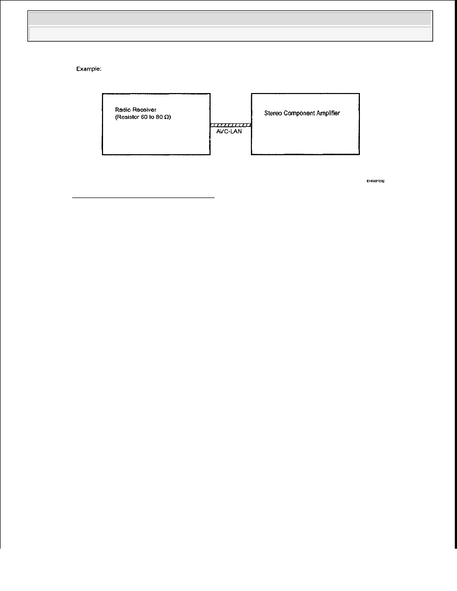
Fig. 133: AVC-LAN - Block Diagram 
Courtesy of TOYOTA MOTOR SALES, U.S.A., INC. 

AVC-LAN, an abbreviation for "Audio Visual Communication Local Area Network", is a united 
standard developed by the manufacturers in affiliation with Toyota Motor Corporation. This 
standard pertains to audio and visual signals as well as switch and communication signals. 

b. Purpose: 

Recently, car audio systems have rapidly developed and the functions have vastly changed. The 
conventional car audio system is being integrated with multi-media interfaces similar to those in 
navigation systems. At the same time, customers are demanding higher quality from their audio 
systems. This is merely an overview of the standardization background. The specific purposes are 
as follows: 

1. To solve sound problems, etc. caused by using components of different manufacturers 

through signal standardization.  

2. To allow each manufacturer to concentrate on developing products they do best. From this, 

reasonably priced products can be produced. 

HINT: 

If a short to +B or short to ground is detected in the AVC-LAN circuit, communication 
is interrupted and the audio system will stop functioning.  

If the audio system has a navigation system installed, the multi-display unit acts as the 
master unit. If the navigation system is not installed, the audio head unit acts as the 
master unit instead. If the radio and navigation assembly is installed, it is the master 
unit.  

4. COMMUNICATION SYSTEM OUTLINE 

a. Components of the audio system communicate with each other via the AVC-LAN.  

b. The master component of the AVC-LAN is a radio receiver with a 60 to 80 ohms resistor. This is 

essential for communication.  

c. If a short circuit or open circuit occurs in the AVC-LAN circuit, communication is interrupted and 

the audio system will stop functioning.  


2009 Toyota Tundra 

2009 ACCESSORIES AND EQUIPMENT Audio/Visual - Tundra


5. DIAGNOSTIC FUNCTION OUTLINE 

a. The audio system has a diagnostic function (the result is indicated on the master unit).  

b. A 3-digit hexadecimal component code (physical address) is allocated to each component on the 

AVC-LAN. Using this code, the component in the diagnostic function can be displayed.  

6. "BLUETOOTH" OUTLINE 

a. "Bluetooth" is a trademark owned by Bluetooth SIG. Inc.  

b. "Bluetooth" is a new wireless connection technology that uses the 2.4 GHz frequency band. This 

makes it possible to connect a cellular phone ("Bluetooth" compatible phone*) to the radio receiver 
(the "Bluetooth" system is built-in) through the handsfree function of the cellular phone, even if it 
is in a pocket or bag. As a result, it is not necessary to directly connect the radio receiver to the 
cellular phone. 

HINT: 

*: Some versions of "Bluetooth" compatible cellular phones may not function.  

The communication performance of "Bluetooth" may vary depending on obstructions or 
radio wave conditions between communication devices, electromagnetic radiation, 
communication device sensitivity, or antenna capacity. 

Fig. 134: Identifying BLUETOOTH Outline 
Courtesy of TOYOTA MOTOR SALES, U.S.A., INC. 

HOW TO PROCEED WITH TROUBLESHOOTING 

HINT: 

Use these procedures to troubleshoot the audio and visual system. 

1. VEHICLE BROUGHT TO WORKSHOP  


2009 Toyota Tundra 

2009 ACCESSORIES AND EQUIPMENT Audio/Visual - Tundra


2. INSPECT BATTERY VOLTAGE 

Standard voltage: 11 to 14 V  

If the voltage is below 11 V, recharge or replace the battery before proceeding. 

3. BASIC INSPECTION 

a. Turn the ignition switch ON.  

b. Check whether or not the radio receiver turns on. 

Result:  

RESULT REFERENCE 

B: Go to step 6 

A: Go to Next Step  

4. CHECK FOR DTC 

a. Check for DTCs and note any codes that are output (see DTC CHECK / CLEAR ). 

HINT: 

If the system cannot enter the diagnostic mode, inspect the AVC-LAN and all the 
components that connect to the AVC-LAN for short circuits and repair or replace the 
problem part.  

Even if the malfunction symptom is not confirmed, check the DTCs. This is because the 
system stores past DTCs.  

b. Delete the DTCs.  

c. Recheck for DTCs by simulating the operation indicated by the DTCs. 

Result:  

RESULT REFERENCE 

B: Go to step 6 

A: Go to Next Step  

Result

Proceed to

Radio receiver turns on

A

Radio receiver does not turn on

B

Result

Proceed to

DTC is output again

A

DTC is not output

B


2009 Toyota Tundra 

2009 ACCESSORIES AND EQUIPMENT Audio/Visual - Tundra


5. DIAGNOSTIC TROUBLE CODE CHART 

a. Find the output code in the DIAGNOSTIC TROUBLE CODE CHART (see DIAGNOSTIC 

TROUBLE CODE CHART ).  

NEXT: Go to step 8 

6. PROBLEM SYMPTOMS TABLE 

a. Refer to the PROBLEM SYMPTOMS TABLE . 

Result:  

RESULT REFERENCE 

B: Go to step 8 

A: Go to Next Step  

7. OVERALL ANALYSIS AND TROUBLESHOOTING 

a. Terminals of ECU (see TERMINALS OF ECU ).  

8. ADJUST, REPAIR OR REPLACE  

9. CONFIRMATION TEST 

NEXT: END  

IDENTIFICATION OF NOISE SOURCE 

1. Radio Description 

a. Radio frequency band 

1. Radio broadcasts use the radio frequency bands shown in the table below. 

Result

Proceed to

Fault is not listed in PROBLEM SYMPTOMS TABLE

A

Fault is listed in PROBLEM SYMPTOMS TABLE

B


2009 Toyota Tundra 

2009 ACCESSORIES AND EQUIPMENT Audio/Visual - Tundra


Content   ..  178  179  180  181   ..