Content .. 1785 1786 1787 1788 ..
Toyota Tundra. Manual - part 1787
35
REMOVE NO. 1 CAMSHAFT BEARING
Fig. 98: Locating No. 1 Camshaft Bearing
Courtesy of TOYOTA MOTOR SALES, U.S.A., INC.
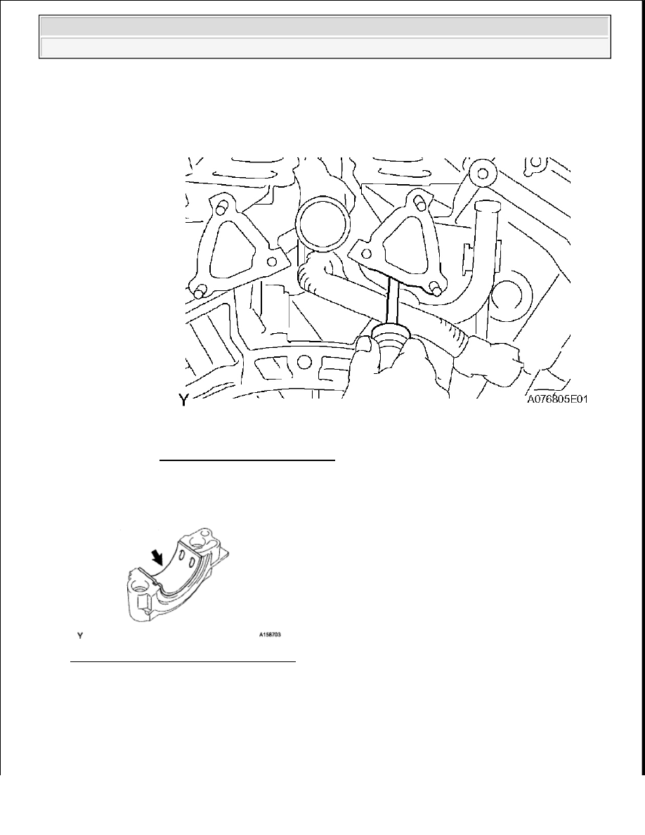
36
REMOVE NO. 2 CAMSHAFT BEARING
and cylinder block with a screwdriver.
Fig. 97: Lifting Cylinder Head
Courtesy of TOYOTA MOTOR SALES, U.S.A., INC.
2009 Toyota Tundra
2009 ENGINE Engine Mechanical (1GR-FE) - Tundra