Content .. 1588 1589 1590 1591 ..
Toyota Tundra. Manual - part 1590
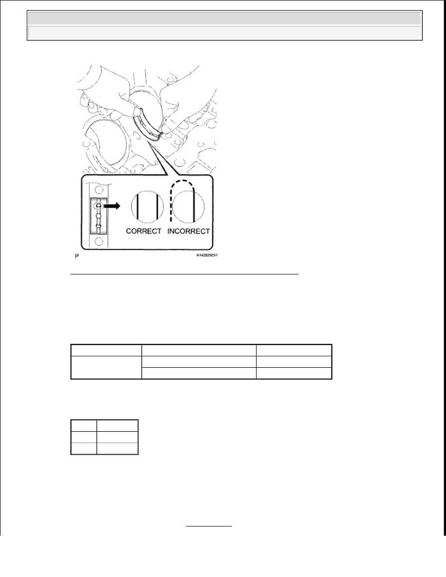
Fig. 204: Identifying J9 Ignition Switch Connector Terminals
Courtesy of TOYOTA MOTOR SALES, U.S.A., INC.
b. Measure the resistance according to the value (s) in the table below.
Standard resistance
RESISTANCE SPECIFIED CONDITIONS
Result
RESULT CHART
B: Go to step 8
A: Go to Next Step
6. REPLACE IGNITION SWITCH ASSEMBLY
a. Replace the ignition switch (See REMOVAL ).
Tester Connection
Switch Condition
Specified Condition
5 (AM2) - 7 (ST2)
Ignition switch position LOCK
10 kohms or higher
Ignition switch position START
Below 1 ohms
Result Proceed to
NG
A
OK
B
2009 Toyota Tundra
2009 ENGINE PERFORMANCE Engine Control System (3UR-FBE) - Tundra