Toyota Tundra. Manual - part 1576


  Index      Toyota     Toyota Tundra (2007-2010 year) - Service and Repair Manual


Search            copyright infringement  


Content   ..  1574  1575  1576  1577   ..


Toyota Tundra. Manual - part 1576


A: Go to step 5 

B: Go to step 6 

4. CHECK HARNESS AND CONNECTOR (CANISTER PUMP MODULE - ECM) 

a. Disconnect the R1 canister pump module connector. 

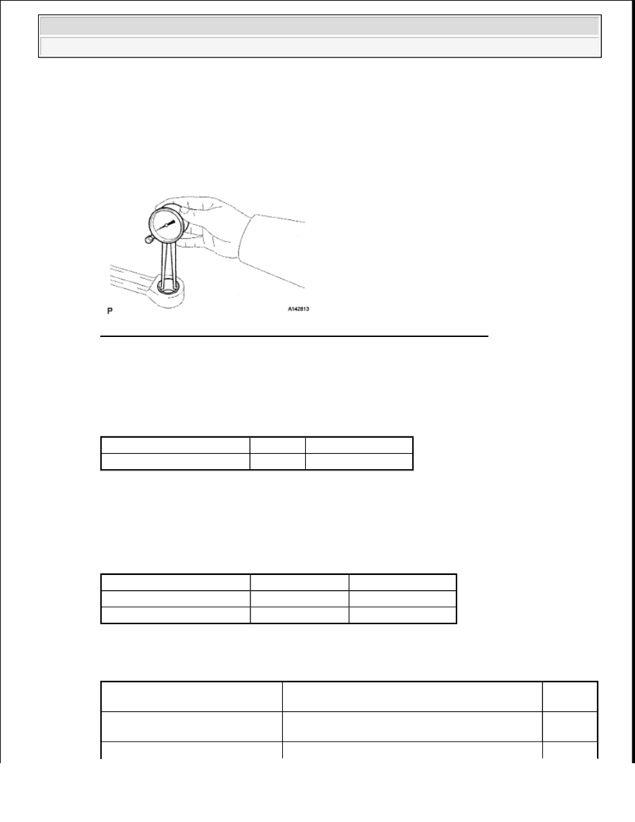
Fig. 179: Identifying Terminals Of R1 Canister Pump Module Connector 
Courtesy of TOYOTA MOTOR SALES, U.S.A., INC. 

b. Measure the resistance according to the value(s) in the table below. 

Standard resistance  

RESISTANCE SPECIFIED CONDITION 

c. Turn the ignition switch to ON.  

d. Measure the voltage according to the value(s) in the table below. 

Standard voltage  

VOLTAGE SPECIFIED CONDITION 

Result  

RESULT REFERENCE 

Tester Connection

Condition Specified Condition

R1-2 (SGND) - Body ground Always

100 ohms or less

Tester Connection

Switch Condition Specified Condition

R1-4 (VCC) - Body ground

Ignition switch ON

4.5 to 5.5 V

R1-3 (VOUT) - Body ground Ignition switch ON

4.5 to 5.5 V

Test Result

Suspected Trouble Area

Proceed 

to

Voltage and resistance within 
standard ranges

Open in canister pressure sensor circuit

A


2009 Toyota Tundra 

2009 ENGINE PERFORMANCE Engine Control System (3UR-FBE) - Tundra


B: Go to step 6 

A: Go to Next Step  

5. REPLACE CHARCOAL CANISTER ASSEMBLY 

a. Replace the canister assembly (see REMOVAL ). 

Fig. 180: Identifying Fuel Tank Vent Hose And Air Inlet Port 
Courtesy of TOYOTA MOTOR SALES, U.S.A., INC. 

NEXT: Go to step 8 

6. REPAIR OR REPLACE HARNESS OR CONNECTOR 

HINT: 

If the exhaust tailpipe has been removed, go to the next step before reinstalling it. 

NEXT: Go to step 8 

7. REPLACE ECM 

a. Replace the ECM (see REMOVAL ).  

8. CHECK WHETHER DTC OUTPUT RECURS (AFTER REPAIR) 

a. Connect the Techstream to the DLC3.  

b. Turn the ignition switch to ON and turn the Techstream ON.  

c. Wait for at least 60 seconds.  

Voltage and resistance outside 
standard ranges

Open in wire harness/connector (ECM - Canister 
pressure sensor)

B

NOTE:

When replacing the canister, check the canister pump module 
interior and related pipes for water, fuel and other liquids. If liquids 
are present, check for disconnections and/or cracks in the following: 
1) the pipe from the air inlet port to the canister pump module; 2) the 
canister filter; and 3) the fuel tank vent hose.


2009 Toyota Tundra 

2009 ENGINE PERFORMANCE Engine Control System (3UR-FBE) - Tundra


d. Enter the following menus: Powertrain/Engine and ECT/Trouble Codes/Pending. 

HINT: 

If no pending DTCs are displayed on the Techstream, the repair has been successfully completed. 

NEXT: COMPLETED  

DTC P0455 EVAPORATIVE EMISSION CONTROL SYSTEM LEAK DETECTED (GROSS LEAK); 
DTC P0456 EVAPORATIVE EMISSION CONTROL SYSTEM LEAK DETECTED (VERY SMALL 
LEAK) 

DTC SUMMARY 

DTC SUMMARY 

DTC

Monitoring 

Item

Malfunction 

Detection 

Condition

Trouble Area

Detection 

Timing

Detection Logic

P0455

EVAP gross leak

Leak detection 
pump creates 
negative pressure 
(vacuum) in 
EVAP system 
and EVAP 
system pressure 
measured. 
Reference 
pressure 
measured at start 
and at end of leak 
check. 
If stabilized 
pressure higher 
than [second 
reference 
pressure x 0.2], 
ECM determines 
that EVAP 
system has large 
leak.

Fuel tank 
cap (loose)  

Leakage 
from EVAP 
line 
(Canister - 
Fuel tank)  

Leakage 
from EVAP 
line (Purge 
VSV - 
Canister)  

Canister 
pump 
module  

Leakage 
from fuel 
tank  

Leakage 
from 
canister  

While ignition 
switch off

2 trip

Leak detection 
pump creates 
negative pressure 
(vacuum) in 
EVAP system 
and EVAP 

Fuel tank 
cap (loose)  

Leakage 
from EVAP 
line 
(Canister - 


2009 Toyota Tundra 

2009 ENGINE PERFORMANCE Engine Control System (3UR-FBE) - Tundra


DESCRIPTION 

The description can be found in the EVAP (Evaporative Emission) System (See DESCRIPTION ). 

INSPECTION PROCEDURE 

Refer to the EVAP SYSTEM . 

MONITOR DESCRIPTION 

5 hours* after the ignition switch is turned off, the leak detection pump creates negative pressure (vacuum) in 
the EVAP system. The ECM monitors for leaks and actuator malfunctions based on the EVAP pressure. 

HINT: 

*: If the engine coolant temperature is not below 35°C (95°F) 5 hours after the ignition switch is turned off, the 
monitor check starts 2 hours later. If it is still not below 35°C (95°F) 7 hours after the ignition switch is turned 
off, the monitor check starts 2.5 hours later. 

MONITOR DESCRIPTION 

P0456

EVAP small leak

system pressure 
measured. 
Reference 
pressure 
measured at start 
and at end of leak 
check. 
If stabilized 
pressure higher 
than second 
reference 
pressure, ECM 
determines that 
EVAP system 
has small leak.

Fuel tank)  

Leakage 
from EVAP 
line (Purge 
VSV - 
Canister)  

Canister 
pump 
module  

Leakage 
from fuel 
tank  

Leakage 
from 
canister  

While ignition 
switch off

2 trip

Sequence

Operation

Description

Duration

-

ECM activation

Activated by soak timer 5, 7 or 9.5 hours after ignition switch 
turned off.

-

A

Atmospheric 
pressure 
measurement

Vent valve turned OFF (vent) and EVAP system pressure 
measured by ECM in order to register atmospheric pressure. 
If pressure in EVAP system not between 70 kPa-a and 110 
kPa-a (525 mmHg-a and 825 mmHg-a), ECM cancels EVAP 
system monitor.

10 

seconds

First reference 

In order to determine reference pressure, leak detection pump 
creates negative pressure (vacuum) through reference orifice 

60 


2009 Toyota Tundra 

2009 ENGINE PERFORMANCE Engine Control System (3UR-FBE) - Tundra


Content   ..  1574  1575  1576  1577   ..