Toyota Tundra. Manual - part 1557


  Index      Toyota     Toyota Tundra (2007-2010 year) - Service and Repair Manual


Search            copyright infringement  


Content   ..  1555  1556  1557  1558   ..


Toyota Tundra. Manual - part 1557


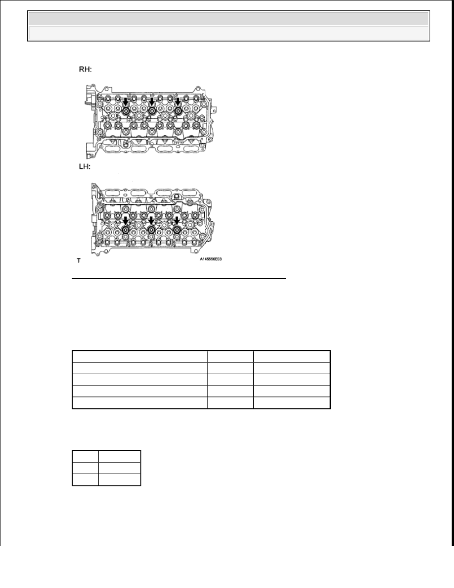
Fig. 131: Identifying Terminals Of D74 ECM Connector 
Courtesy of TOYOTA MOTOR SALES, U.S.A., INC. 

b. Measure the resistance according to the value(s) in the table below. 

Standard resistance  

RESISTANCE SPECIFIED CONDITION 

Result  

RESULT REFERENCE 

B: Go to step 3 

A: Go to Next Step  

Tester Connection

Condition Specified Condition

D74-94 (KNK1) - D74-93 (EKNK)

20°C (68°F) 120 to 280 kohms

D74-117 (KNK2) - D74-116 (EKN2) 20°C (68°F) 120 to 280 kohms
D74-96 (KNK3) - D74-95 (EKN3)

20°C (68°F) 120 to 280 kohms

D74-119 (KNK4) - D74-118 (EKN4) 20°C (68°F) 120 to 280 kohms

Result Proceed to

NG

A

OK

B


2009 Toyota Tundra 

2009 ENGINE PERFORMANCE Engine Control System (3UR-FBE) - Tundra


2. CHECK HARNESS AND CONNECTOR (ECM - KNOCK SENSOR) 

a. Disconnect the D74 ECM connector. 

Fig. 132: Identifying Terminals Of D74 ECM Connector 
Courtesy of TOYOTA MOTOR SALES, U.S.A., INC. 

b. Disconnect the a3, a4, a5 or a6 knock sensor connector.  

c. Measure the resistance according to the value(s) in the table below. 

Standard resistance  

RESISTANCE SPECIFIED CONDITION 

NG: REPAIR OR REPLACE HARNESS OR CONNECTOR  

OK: REPLACE KNOCK SENSOR (See REMOVAL ) 

3. INSPECT ECM 

Tester Connection

Condition Specified Condition

a5-2 - D74-94 (KNK1)

Always

Below 1 ohms

a5-1 - D74-93 (EKNK)

Always

Below 1 ohms

a6-2 - D74-117 (KNK2)

Always

Below 1 ohms

a6-1 - D74-116 (EKN2)

Always

Below 1 ohms

a3-2 - D74-96 (KNK3)

Always

Below 1 ohms

a3-1 - D74-95 (EKN3)

Always

Below 1 ohms

a4-2 - D74-119 (KNK4)

Always

Below 1 ohms

a4-1 - D74-118 (EKN4)

Always

Below 1 ohms

a5-2 or D74-94 (KNK1) - Body ground

Always

10 kohms or higher

a5-1 or D74-93 (EKNK) -Body ground

Always

10 kohms or higher

a6-2 or D74-117 (KNK2) - Body ground Always

10 kohms or higher

a6-1 or D74-116 (EKN2) - Body ground Always

10 kohms or higher

a3-2 or D74-96 (KNK3) -Body ground

Always

10 kohms or higher

a3-1 or D74-95 (EKN3) - Body ground

Always

10 kohms or higher

a4-2 or D74-119 (KNK4) - Body ground Always

10 kohms or higher

a4-1 or D74-118 (EKN4) - Body ground Always

10 kohms or higher


2009 Toyota Tundra 

2009 ENGINE PERFORMANCE Engine Control System (3UR-FBE) - Tundra


a. Disconnect the a3, a4, a5 or a6 knock sensor connector.  

b. Turn the ignition switch to ON.  

c. Measure the voltage according to the value(s) in the table below. 

Standard voltage  

VOLTAGE SPECIFIED CONDITION 

Fig. 133: Identifying Terminals Of Knock Sensor Connector 
Courtesy of TOYOTA MOTOR SALES, U.S.A., INC. 

NG: REPLACE ECM (See REMOVAL ) 

OK: CHECK FOR INTERMITTENT PROBLEMS (See CHECK FOR INTERMITTENT 
PROBLEMS
 ) 

DTC P0335 CRANKSHAFT POSITION SENSOR "A" CIRCUIT; DTC P0337 CRANKSHAFT 
POSITION SENSOR "A" CIRCUIT LOW INPUT; DTC P0338 CRANKSHAFT POSITION SENSOR 
"A" CIRCUIT HIGH INPUT; DTC P0339 CRANKSHAFT POSITION SENSOR "A" CIRCUIT 
INTERMITTENT 

DESCRIPTION 

The crankshaft position (CKP) sensor system consists of a crankshaft position sensor plate and Magnetic 
Resistance Element (MRE) type sensor. The crankshaft position sensor plate has 34 teeth at 10° intervals (2 
teeth are missing for detecting top dead center), and is installed to the rear end of the crankshaft. The crankshaft 
position sensor outputs 34 rotation signals per engine revolution. The ECM uses the G2 signal to distinguish 
between the cylinders, and uses the NE signal to detect the crankshaft position and engine speed. 

Tester Connection Switch Condition Specified Condition

1 - 2

Ignition switch ON

4.5 to 5.5 V


2009 Toyota Tundra 

2009 ENGINE PERFORMANCE Engine Control System (3UR-FBE) - Tundra


DTC DETECTION CONDITION AND TROUBLE AREA REFERENCE CHART 

Reference: Inspection using an oscilloscope. 

Fig. 134: Identifying NE And G2 Signal Waveform 
Courtesy of TOYOTA MOTOR SALES, U.S.A., INC. 

DTC

DTC Detection Condition

Trouble Area

P0335

No CKP sensor signal to 
ECM while cranking (1 trip 
detection logic)  

No CKP sensor signal to 
ECM at engine speed of less 
than 450 RPM (1 trip 
detection logic)  

Open or short in CKP sensor 
circuit  

CKP sensor  

CKP sensor plate  

ECM  

P0337

Output voltage of CKP sensor 0.3 
V or less for 4 seconds (1 trip 
detection logic)

Open or short in CKP sensor 
circuit  

CKP sensor  

CKP sensor plate  

ECM  

P0338

Output voltage of CKP sensor 4.7 
V or more for 4 seconds (1 trip 
detection logic)

Open or short in CKP sensor 
circuit  

CKP sensor  

CKP sensor plate  

ECM  

P0339

Under conditions (a), (b) and (c), 
no CKP sensor signal to ECM for 
0.05 seconds or more (1 trip 
detection logic): 

a. Engine speed 1000 RPM or 

more  

b. Starter signal OFF  

c. 3 seconds or more have 

elapsed since starter signal 
switched from ON to OFF  

Open or short in CKP sensor 
circuit  

CKP sensor  

CKP sensor plate  

ECM  


2009 Toyota Tundra 

2009 ENGINE PERFORMANCE Engine Control System (3UR-FBE) - Tundra


Content   ..  1555  1556  1557  1558   ..