Toyota Tundra. Manual - part 1285


  Index      Toyota     Toyota Tundra (2007-2010 year) - Service and Repair Manual


Search            copyright infringement  


Content   ..  1283  1284  1285  1286   ..


Toyota Tundra. Manual - part 1285


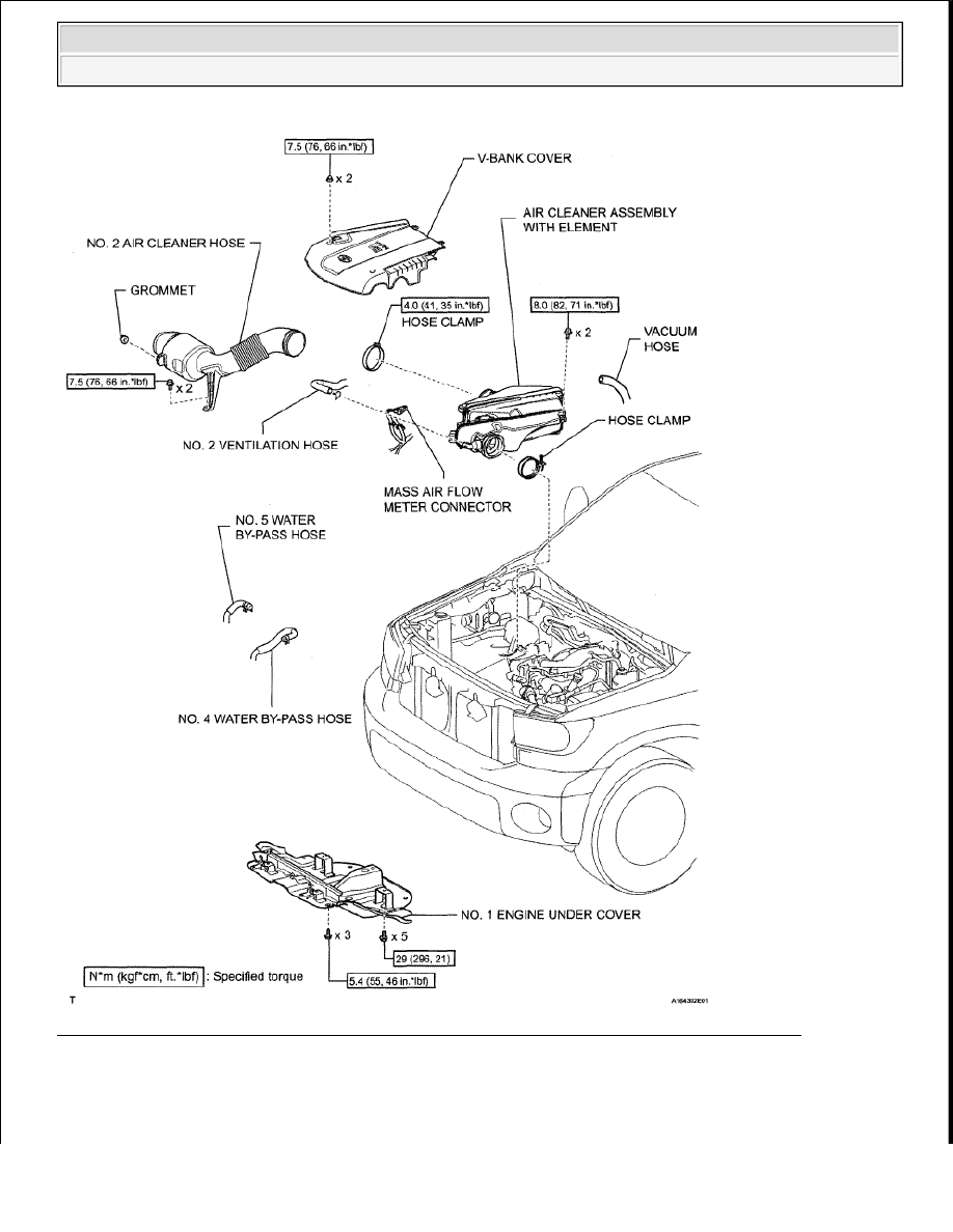
Fig. 329: Identifying VVT Sensor Replacement Components & Torque Specifications (2 Of 3) 


2008 Toyota Tundra 

2008 ENGINE PERFORMANCE Engine Control System (1GR-FE) - Tundra


Fig. 330: Identifying VVT Sensor Replacement Components & Torque Specifications (3 Of 3) 

REMOVAL 

1. DISCONNECT CABLE FROM NEGATIVE BATTERY TERMINAL 

NOTE:

Some systems need to be initialized after the cable is reconnected 
(see INITIALIZATION ).  

After the ignition switch is turned OFF, the navigation system 
requires approximately 90 seconds to record various types of 
memory and settings. As a result, after turning the ignition switch 


2008 Toyota Tundra 

2008 ENGINE PERFORMANCE Engine Control System (1GR-FE) - Tundra


2. REMOVE NO. 1 ENGINE UNDER COVER (See REMOVAL )  

3. DRAIN ENGINE COOLANT . (See REPLACEMENT ).  

4. REMOVE FRONT WIPER MOTOR AND LINK ASSEMBLY 

a. Remove the front wiper motor and link assembly. (See REMOVAL ).  

5. REMOVE FRONT COWL TOP OUTER PANEL SUB-ASSEMBLY . (See INTAKE SYSTEM ).  

6. REMOVE V-BANK COVER . (See INTAKE SYSTEM ).  

7. REMOVE NO. 2 AIR CLEANER HOSE . (See REMOVAL ).  

8. REMOVE AIR CLEANER ASSEMBLY WITH ELEMENT . (See REMOVAL ).  

9. REMOVE VVT SENSOR (for Bank 1) 

a. Disconnect the sensor connector.  

b. Remove the bolt and sensor. 

Fig. 331: Locating Bolt & Sensor 

10. REMOVE VVT SENSOR (for Bank 2) 

a. Disconnect the No. 4 and No. 5 water by-pass hoses.  

b. Disconnect the sensor connector. 

Fig. 332: Locating Water By-Pass Hoses No. 4 & No. 5 

c. Remove the bolt and sensor. 

OFF, wait 90 seconds or more before disconnecting the cable from 
the negative (-) battery terminal.  


2008 Toyota Tundra 

2008 ENGINE PERFORMANCE Engine Control System (1GR-FE) - Tundra


Fig. 333: Locating Bolt & Sensor 

INSTALLATION 

1. INSTALL VVT SENSOR (for Bank 2) 

a. Apply a light coat of engine oil to the O-ring of the VVT sensor.  

b. Install the VVT sensor with the bolt. 

Torque: 8.0 N*m (82 kgf*cm, 71 in.*lbf)  

c. Connect the sensor connector. 

Fig. 334: Locating VVT Sensor & Bolt 

d. Connect the No. 4 and No. 5 water by-pass hoses. 

Fig. 335: Locating Water By-Pass Hoses No. 4 & No. 5 


2008 Toyota Tundra 

2008 ENGINE PERFORMANCE Engine Control System (1GR-FE) - Tundra


Content   ..  1283  1284  1285  1286   ..