Toyota Tundra. Manual - part 1275


  Index      Toyota     Toyota Tundra (2007-2010 year) - Service and Repair Manual


Search            copyright infringement  


Content   ..  1273  1274  1275  1276   ..


Toyota Tundra. Manual - part 1275
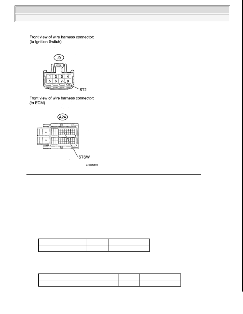


Fig. 280: Identifying J9 Ignition Switch Connector & A24 ECM Connector Terminals 

OK : Go to next step.  

12. CHECK HARNESS AND CONNECTOR (PNP SWITCH - ECM) 

a. Disconnect the D35 PNP switch connector.  

b. Disconnect the D74 ECM connector.  

c. Measure the resistance according to the value (s) in the table below. 

Standard resistance (Check for open)  

TESTER CONNECTION SPECIFIED CONDITION 

Standard resistance (Check for short)  

TESTER CONNECTION SPECIFIED CONDITION 

Tester Connection

Condition Specified Condition

D35-4 - D74-16 (STAR) Always

Below 1 ohms

Tester Connection

Condition Specified Condition

D35-4 or D74-16 (STAR) - Body ground Always

10 kohms or higher


2008 Toyota Tundra 

2008 ENGINE PERFORMANCE Engine Control System (1GR-FE) - Tundra


NG : REPAIR OR REPLACE HARNESS OR CONNECTOR  

Fig. 281: Identifying D35 PNP Switch Connector & D74 ECM Connector 

OK : REPLACE ECM (See REMOVAL ) 

ACIS CONTROL CIRCUIT 

DESCRIPTION 

This circuit opens and closes the Intake Air Control Valve (IACV) in response to changes in the engine load in 
order to increase the intake efficiency (ACIS: Acoustic Control Induction System). 

When the engine speed is between 2200 RPM and 4100 RPM and the throttle valve opening angle is 60° or 
more, the ECM supplies current to the VSV (ON status), to close the IACV. Under other conditions, the VSV is 
usually OFF and the IACV is open. 


2008 Toyota Tundra 

2008 ENGINE PERFORMANCE Engine Control System (1GR-FE) - Tundra


Fig. 282: Throttle Valve Opening Angle Graph 

WIRING DIAGRAM 

Fig. 283: ACIS Control Circuit - Wiring Diagram 

INSPECTION PROCEDURE 

1. PERFORM ACTIVE TEST USING TECHSTREAM (OPERATE VSV FOR ACIS) 

a. Disconnect the vacuum hose.  

b. Connect the Techstream to the DLC3.  

c. Turn the ignition switch ON and turn the Techstream ON.  

d. Enter the following menus: Powertrain/Engine and ECT/Active Test/Active the VSV for Intake 

Control. Operate the VSV for ACIS.  

e. Check the VSV operation when it is operated using the Techstream. 

Standard  


2008 Toyota Tundra 

2008 ENGINE PERFORMANCE Engine Control System (1GR-FE) - Tundra


ACTIVE TEST CHART 

Fig. 284: Checking VSV Operation 

Result  

RESULT CHART 

f. Reconnect the vacuum hose.  

B : Go to step 4 

A : Go to next step.  

2. CHECK VSV FOR ACIS (OPERATION) 

a. Inspect VSV for ACIS. (See ON-VEHICLE INSPECTION ).  

NG : REPLACE VSV FOR ACIS  

OK : Go to next step.  

3. CHECK HARNESS AND CONNECTOR (VSV FOR ACIS - ECM, VSV FOR ACIS - EFI NO. 2 

FUSE) 

a. Check the wire harness and connectors between the VSV for ACIS and ECM. 

1. Disconnect the D61 VSV for ACIS connector.  

2. Disconnect the D74 ECM connector.  

3. Measure the resistance according to the value (s) in the table below. 

Standard resistance (Check for open)  

Tester Operation

Specified Condition

VSV ON

Air from port E flows out through port F

VSV OFF

Air from port E flows out through air filter

Result Proceed To

NG

A

OK

B


2008 Toyota Tundra 

2008 ENGINE PERFORMANCE Engine Control System (1GR-FE) - Tundra


Content   ..  1273  1274  1275  1276   ..