Toyota Tundra. Manual - part 1217


  Index      Toyota     Toyota Tundra (2007-2010 year) - Service and Repair Manual


Search            copyright infringement  


Content   ..  1215  1216  1217  1218   ..


Toyota Tundra. Manual - part 1217


NG : REPLACE STOP LIGHT SWITCH ASSEMBLY . (See STOP LIGHT SWITCH ). 

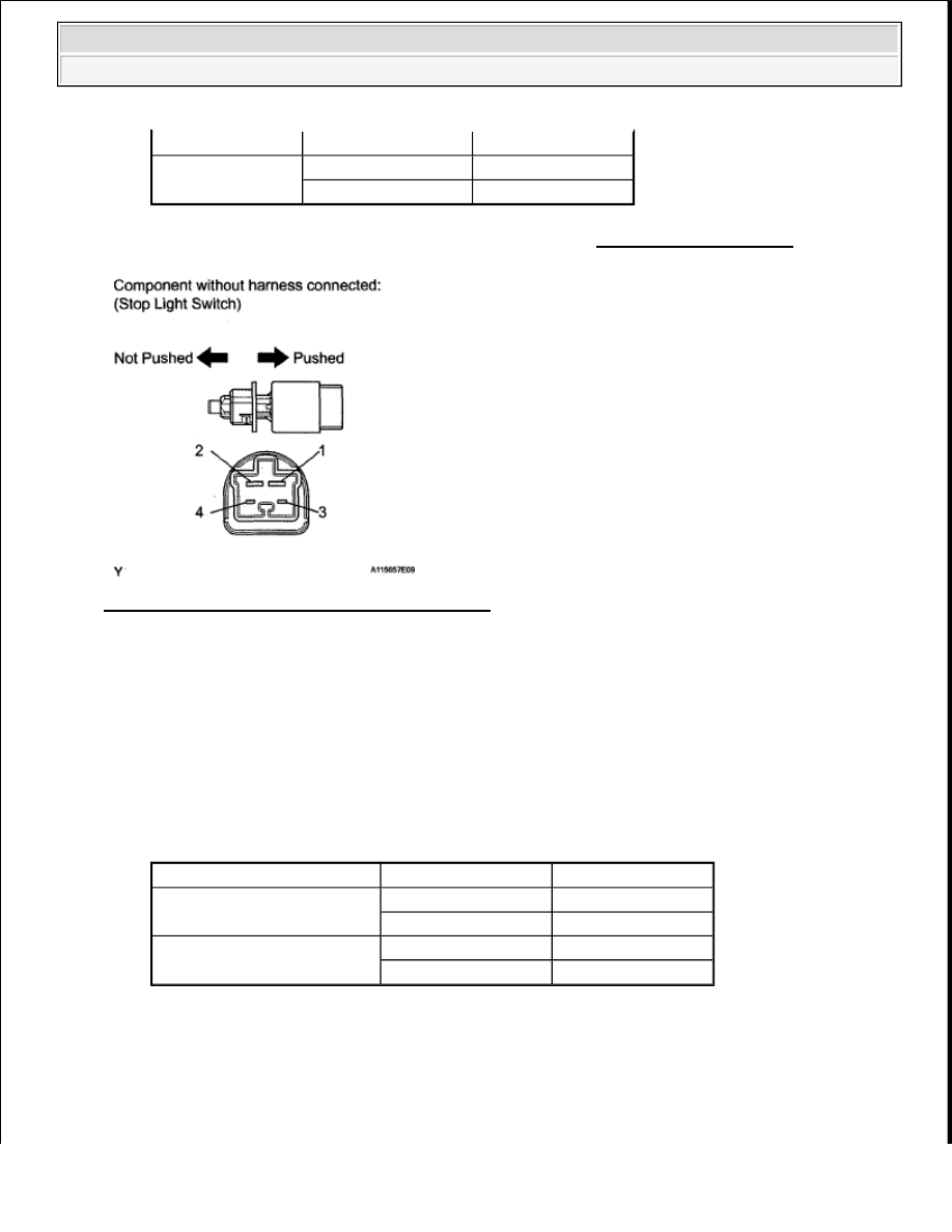
Fig. 170: Inspecting Stop Light Switch Assembly 

OK : Go to next step.  

3. CHECK ECM (STP AND ST1 - VOLTAGE) 

a. Disconnect the A24 ECM connector.  

b. Turn the ignition switch ON.  

c. Measure the voltage according to the value(s) in the table below. 

Standard voltage  

TESTER CONNECTION SPECIFIED CONDITION 

NG : REPAIR OR REPLACE HARNESS AND CONNECTOR  

Switch pin pushed

10 kohms or higher

3 - 4

Switch pin not pushed 10 kohms or higher

Switch pin pushed

Below 1 ohms

Tester Connection

Condition

Specified Condition

A24-35 (ST1-) - Body ground

Brake pedal released

11 to 14 V

Brake pedal depressed

0 to 3 V

A24-36 (STP) - Body ground

Brake pedal released

0 to 3 V

Brake pedal depressed

11 to 14 V


2008 Toyota Tundra 

2008 ENGINE PERFORMANCE Engine Control System (1GR-FE) - Tundra


Fig. 171: Identifying Brake Pedal Position 

OK : REPLACE ECM (See REMOVAL ) 

4. INSPECT FUSE (STOP, IGN) 

a. Remove the STOP and IGN fuses from the engine room relay block, junction block.  

b. Measure the resistance according to the value(s) in the table below. 

Standard resistance  

TESTER CONNECTION SPECIFIED CONDITION 

NG : CHECK FOR SHORTS IN ALL HARNESSES AND CONNECTORS CONNECTED TO 
FUSE AND REPLACE FUSE
  

Tester Connection Condition Specified Condition

STOP fuse

Always

Below 1 ohms

IGN fuse


2008 Toyota Tundra 

2008 ENGINE PERFORMANCE Engine Control System (1GR-FE) - Tundra


Fig. 172: Identifying STOP & IGN Fuses 

OK : REPAIR OR REPLACE HARNESS OR CONNECTOR  

DTC P0505 IDLE CONTROL SYSTEM MALFUNCTION 

DESCRIPTION 

The idling speed is controlled by the ETCS (Electronic Throttle Control System). The ETCS is comprised of: 1) 
the one valve type throttle body; 2) the throttle actuator, which operates the throttle valve; 3) the Throttle 
Position (TP) sensor, which detects the opening angle of the throttle valve; 4) the Accelerator Pedal Position 
(APP) sensor, which detects the accelerator pedal position; and 5) the ECM, which controls the ETCS. Based on 
the target idling speed, the ECM controls the throttle actuator to provide the proper throttle valve opening angle. 

DTC TROUBLE DETECTION CONDITION CHART 

MONITOR DESCRIPTION 

The ECM monitors the idling speed and idling air flow volume to conduct Idle Speed Control (ISC). The ECM 
determines that the ISC system is malfunctioning if the following conditions apply: 

The learned idling air flow volume remains at the maximum or minimum volume for 5 seconds during a 
drive cycle.  

DTC 

No.

DTC Detection Condition

Trouble Area

P0505

Idling speed continues to vary greatly from target idling speed (2 trip 
detection logic)

ETCS  

Air induction 
system  

PCV hose 
connections  

ECM  


2008 Toyota Tundra 

2008 ENGINE PERFORMANCE Engine Control System (1GR-FE) - Tundra


After driving at 6.25 mph (10 km/h) or more, the actual engine idling speed varies from the target idling 
speed by between 100 RPM and 200 RPM, 5 times or more during a drive cycle.  

Example: 

If the actual idling speed varies from the target idling speed by more than 200 RPM* 5 times during a drive 
cycle, the ECM illuminates the MIL and sets the DTC. 

HINT: 

*: Threshold idling speed varies with engine load. 

Fig. 173: Idling Speed Graph 

MONITOR STRATEGY 

MONITOR STRATEGY 

Related DTCs

P0505: ISC function

Required Sensors/Components 
(Main)

ETCS

Required Sensors/Components 
(Related)

Crankshaft position sensor, Engine coolant temperature sensor, and 
Vehicle speed sensor

Frequency of Operation

Once per driving cycle

Duration

10 minutes

MIL Operation

2 driving cycles


2008 Toyota Tundra 

2008 ENGINE PERFORMANCE Engine Control System (1GR-FE) - Tundra


Content   ..  1215  1216  1217  1218   ..