Toyota Tundra. Manual - part 1216


  Index      Toyota     Toyota Tundra (2007-2010 year) - Service and Repair Manual


Search            copyright infringement  


Content   ..  1214  1215  1216  1217   ..


Toyota Tundra. Manual - part 1216


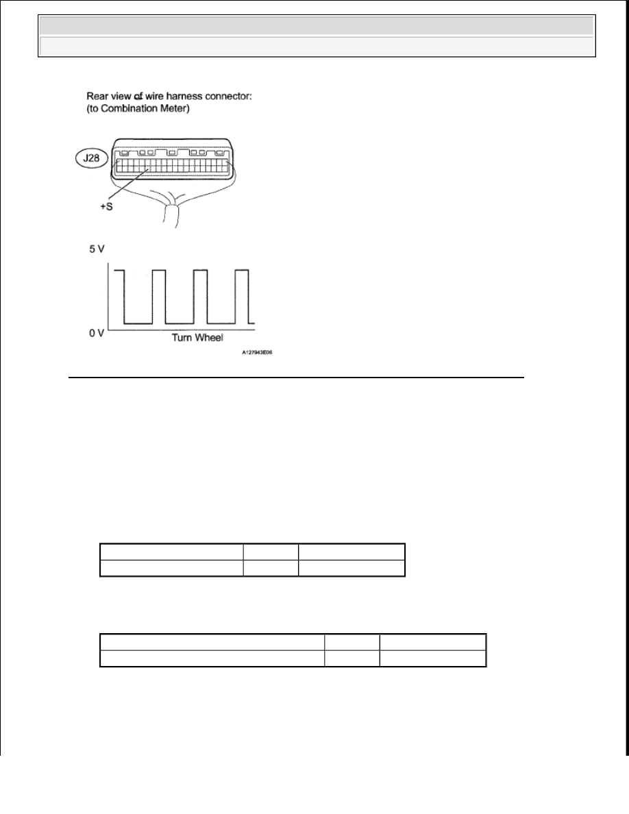
Fig. 166: Checking Voltage Between Terminal Of Combination Meter & Body Ground 

OK : Go to next step.  

5. CHECK HARNESS AND CONNECTOR (COMBINATION METER ASSEMBLY - ECM) 

a. Disconnect the J28 combination meter connector.  

b. Disconnect the A24 ECM connector.  

c. Measure the resistance according the value(s) in the table below. 

Standard resistance (Check for open)  

TESTER CONNECTION SPECIFIED CONDITION 

Standard resistance (Check for open)  

TESTER CONNECTION SPECIFIED CONDITION 

NG : REPAIR OR REPLACE HARNESS OR CONNECTOR  

Tester Connection

Condition Specified Condition

J28-35 (+S) - A24-13 (SPD) Always

Below 1 ohms

Tester Connection

Condition Specified Condition

J28-35 (+S) or A24-13 (SPD) - Body ground Always

10 kohms or higher


2008 Toyota Tundra 

2008 ENGINE PERFORMANCE Engine Control System (1GR-FE) - Tundra


Fig. 167: Identifying J28 Combination Meter Connector Terminals 

OK : REPLACE ECM (See REMOVAL ) 

DTC P0504 BRAKE SWITCH "A"/"B" CORRELATION 

DESCRIPTION 

The stop light switch is a duplex system that transmits two signals: STP and ST1-. These two signals are used 
by the ECM to monitor whether or not the brake system is working properly. If the signals, which indicate the 
brake pedal is being depressed and released, are detected simultaneously, the ECM interprets this as a 
malfunction in the stop light switch and sets the DTC. 

HINT: 

The normal conditions are as shown in the table below. The signals can be read using the Techstream. 

BRAKE PEDAL CONDITION CHART 

DTC TROUBLE DETECTION CONDITION CHART 

Signal

Brake Pedal Released

In Transition

Brake Pedal Depressed

STP

OFF

ON

ON

ST1-

ON

ON

OFF

DTC 

No.

DTC Detection Condition

Trouble Area

Conditions (a), (b) and (c) continue for 0.5 seconds or more 

Short in stop light switch 


2008 Toyota Tundra 

2008 ENGINE PERFORMANCE Engine Control System (1GR-FE) - Tundra


WIRING DIAGRAM 

Fig. 168: Brake Switch Wiring Diagram 

INSPECTION PROCEDURE 

HINT: 

Read freeze frame data using the Techstream. Freeze frame data records the engine condition when 
malfunctions are detected. When troubleshooting, freeze frame data can help determine if the vehicle was 
moving or stationary, if the engine was warmed up or not, if the air-fuel ratio was lean or rich, and other 
data from the time the malfunction occurred.  

STP signal conditions can be checked using the Techstream. 

a. Connect the Techstream to the DLC3.  

b. Turn the ignition switch ON.  

c. Turn the Techstream ON.  

d. Enter the following menus: Powertrain/Engine and ECT/All Data/Stop Light Switch.  

e. Check the STP signal when the brake pedal is depressed and released. 

BRAKE PEDAL CONDITION CHART 

P0504

(1 trip detection logic): 

a. Ignition switch ON  

b. Brake pedal released  

c. STP signal OFF when ST1- signal OFF  

signal circuit  

STOP fuse  

IGN fuse  

Stop light switch  

ECM  

Brake Pedal Operation Specified Condition


2008 Toyota Tundra 

2008 ENGINE PERFORMANCE Engine Control System (1GR-FE) - Tundra


1. CHECK STOP LIGHT SWITCH ASSEMBLY (TERMINAL B VOLTAGE) 

a. Disconnect the A4 stop light switch connector.  

b. Measure the voltage according to the value(s) in the table below. 

Standard voltage  

TESTER CONNECTION SPECIFIED CONDITION 

NG : Go to step 4 

Fig. 169: Identifying A4 Stop Light Switch Connector Terminals 

OK : Go to next step.  

2. INSPECT STOP LIGHT SWITCH ASSEMBLY 

a. Remove the stop light switch.  

b. Measure the resistance according to the value(s) in the table below. 

Standard resistance  

TESTER CONNECTION SPECIFIED CONDITION 

Depressed

STP signal ON

Released

STP signal OFF

Tester Connection Switch Condition Specified Condition

A4-2 - Body ground

Always

11 to 14 V

A4-3 - Body ground Ignition switch ON

11 to 14 V

Tester Connection

Switch Condition

Specified Condition

1 - 2

Switch pin not pushed

Below 1 ohms


2008 Toyota Tundra 

2008 ENGINE PERFORMANCE Engine Control System (1GR-FE) - Tundra


Content   ..  1214  1215  1216  1217   ..