Toyota Tundra. Manual - part 1200


  Index      Toyota     Toyota Tundra (2007-2010 year) - Service and Repair Manual


Search            copyright infringement  


Content   ..  1198  1199  1200  1201   ..


Toyota Tundra. Manual - part 1200


HINT: 

Read freeze frame data using the Techstream. Freeze frame data records the engine condition when 
malfunctions are detected. When troubleshooting, freeze frame data can help determine if the vehicle was 
moving or stationary, if the engine was warmed up or not, if the air-fuel ratio was lean or rich, and other data 
from the time the malfunction occurred. 

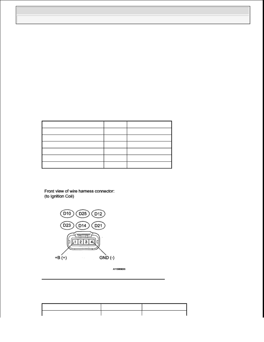
1. INSPECT IGNITION COIL ASSEMBLY (POWER SOURCE) 

a. Disconnect the ignition coil connector.  

b. Measure the resistance according to the value(s) in the table below. 

Standard resistance (Check for open)  

TESTER CONNECTION SPECIFIED CONDITION 

c. Measure the voltage according to the value(s) in the table below. 

Fig. 133: Identifying Ignition Coil Connector Terminals 

Standard voltage (Check for open)  

TESTER CONNECTION SPECIFIED CONDITION 

Tester Connection

Condition Specified Condition

D10-4 (GND) - Body ground Always

Below 1 ohms

D25-4 (GND) - Body ground Always

Below 1 ohms

D12-4 (GND) - Body ground Always

Below 1 ohms

D23-4 (GND) - Body ground Always

Below 1 ohms

D14-4 (GND) - Body ground Always

Below 1 ohms

D21-4 (GND) - Body ground Always

Below 1 ohms

Tester Connection

Switch Condition Specified Condition


2008 Toyota Tundra 

2008 ENGINE PERFORMANCE Engine Control System (1GR-FE) - Tundra


NG : REPAIR OR REPLACE HARNESS OR CONNECTOR  

OK : Go to next step  

2. CHECK HARNESS AND CONNECTOR (IGNITION COIL ASSEMBLY - ECM) 

a. Disconnect the ignition coil connector.  

b. Disconnect the D74 ECM connector.  

c. Measure the resistance according to the value(s) in the table below. 

Standard resistance (Check for open)  

TESTER CONNECTION SPECIFIED CONDITION 

D10-1 (+B) - D10-4 (GND) Ignition switch ON

11 to 14 V

D25-1 (+B) - D25-4 (GND) Ignition switch ON

11 to 14 V

D12-1 (+B) - D12-4 (GND) Ignition switch ON

11 to 14 V

D23-1 (+B) - D23-4 (GND) Ignition switch ON

11 to 14 V

D14-1 (+B) - D14-4 (GND) Ignition switch ON

11 to 14 V

D21-1(+B) - D21-4 (GND) Ignition switch ON

11 to 14 V

Tester Connection

Condition Specified Condition

D10-2 (IGF) - D74-104 (IGF1) Always

Below 1 ohms

D25-2 (IGF) - D74-104 (IGF1) Always

Below 1 ohms

D12-2 (IGF) - D74-104 (IGF1) Always

Below 1 ohms

D23-2 (IGF) - D74-104 (IGF1) Always

Below 1 ohms

D14-2 (IGF) - D74-104 (IGF1) Always

Below 1 ohms

D21-2 (IGF) - D74-104 (IGF1) Always

Below 1 ohms

D10-3 (IGT1) - D74-40 (IGT1) Always

Below 1 ohms

D25-3 (IGT2) - D74-39 (IGT2) Always

Below 1 ohms

D12-3 (IGT3) - D74-38 (IGT3) Always

Below 1 ohms

D23-3 (IGT4) - D74-37 (IGT4) Always

Below 1 ohms

D14-3 (IGT5) - D74-36 (IGT5) Always

Below 1 ohms

D21-3 (IGT6) - D74-35 (IGT6) Always

Below 1 ohms


2008 Toyota Tundra 

2008 ENGINE PERFORMANCE Engine Control System (1GR-FE) - Tundra


Fig. 134: Identifying D74 ECM Connector 

Standard resistance (Check for short)  

TESTER CONNECTION SPECIFIED CONDITION 

NG : REPAIR OR REPLACE HARNESS OR CONNECTOR  

OK : Go to next step  

3. CHECK WHETHER DTC OUTPUT RECURS (DTC P0351, P0352, P0353, P0354, P0355 OR 

P0356) 

Tester Connection

Condition Specified Condition

D10-2 (IGF) or D74-104 (IGF1) - Body ground Always

10 kohms or higher

D25-2 (IGF) or D74-104 (IGF1) - Body ground Always

10 kohms or higher

D12-2 (IGF) or D74-104 (IGF1) - Body ground Always

10 kohms or higher

D23-2 (IGF) or D74-104 (IGF1) - Body ground Always

10 kohms or higher

D14-2 (IGF) or D74-104 (IGF1) - Body ground Always

10 kohms or higher

D21-2 (IGF) or D74-104 (IGF1) - Body ground Always

10 kohms or higher

D10-3 (IGT1) or D74-40 (IGT1) - Body ground Always

10 kohms or higher

D25-3 (IGT2) or D74-39 (IGT2) - Body ground Always

10 kohms or higher

D12-3 (IGT3) or D74-38 (IGT3) - Body ground Always

10 kohms or higher

D23-3 (IGT4) or D74-37 (IGT4) - Body ground Always

10 kohms or higher

D14-3 (IGT5) or D74-36 (IGT5) - Body ground Always

10 kohms or higher

D21-3 (IGT6) or D74-35 (IGT6) - Body ground Always

10 kohms or higher


2008 Toyota Tundra 

2008 ENGINE PERFORMANCE Engine Control System (1GR-FE) - Tundra


a. Connect the Techstream to the DLC3.  

b. Turn the ignition switch ON and turn the Techstream ON.  

c. Clear DTCs (See DTC CHECK/CLEAR ).  

d. Shuffle arrangement of the ignition coils (among No. 1 to No. 6 cylinders). 

e. Perform a simulation test.  

f. Check DTCs displayed on the Techstream. 

Result  

RESULT CHART 

B : REPLACE IGNITION COIL ASSEMBLY . (See IGNITION COIL AND SPARK PLUG ). 

A : REPLACE ECM . (See REMOVAL). 

DTC P0412 SECONDARY AIR INJECTION SYSTEM SWITCHING VALVE "A" CIRCUIT; DTC 
P0415 SECONDARY AIR INJECTION SYSTEM SWITCHING VALVE "B" CIRCUIT 

DESCRIPTION 

The Secondary Air Injection (AIR) system consists of an air pump, the Air Switching Valve (ASV), a pressure 
sensor, the Air Injection Control Driver (AID) and the ECM. For a short time after cold engine starts, the AIR 
system pumps secondary air to the exhaust port of the cylinder head to purify the exhaust emissions. The 
secondary air is supplied by the air pump and is pumped to the exhaust port through the ASV. 

The AID drives the ASV and the air pump according to command signals transmitted by the ECM. The pressure 
sensor detects the pressure in the secondary air passage when the AIR system is ON and OFF, and transmits a 
pressure signal to the ECM. 

The AID is not only equipped to drive the pump and valve, but also with a diagnosis function to detect 
malfunctions in the AIR system circuit. 

HINT: 

As a large current is required to drive the air pump and ASV, an AID is installed to this system. 

NOTE:

Do not shuffle the connectors.

Display (DTC Output)

Proceed To

Same DTC output

A

Different ignition coil DTC output

B


2008 Toyota Tundra 

2008 ENGINE PERFORMANCE Engine Control System (1GR-FE) - Tundra


Content   ..  1198  1199  1200  1201   ..