Toyota Tundra. Manual - part 1196


  Index      Toyota     Toyota Tundra (2007-2010 year) - Service and Repair Manual


Search            copyright infringement  


Content   ..  1194  1195  1196  1197   ..


Toyota Tundra. Manual - part 1196


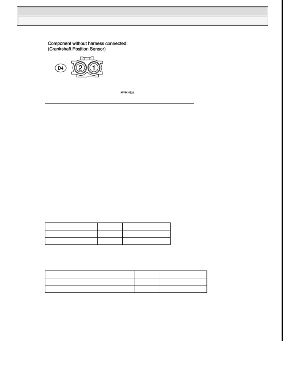
Fig. 121: Identifying D4 Crankshaft Position Sensor Connector 

HINT: 

The terms "Cold" and "Hot" refer to the temperature of the sensor. Cold means approximately -10 
to 50°C (14 to 122°F). Hot means approximately 50 to 100°C (122 to 212°F). 

NG : REPLACE CRANKSHAFT POSITION SENSOR (See REMOVAL ) 

OK : Go to next step  

3. CHECK HARNESS AND CONNECTOR (CRANKSHAFT POSITION SENSOR - ECM) 

a. Disconnect the D4 CKP sensor connector.  

b. Disconnect the D74 ECM connector.  

c. Measure the resistance according to the value(s) in the table below. 

Standard resistance (Check for open)  

TESTER CONNECTION SPECIFIED CONDITION 

Standard resistance (Check for short)  

TESTER CONNECTION SPECIFIED CONDITION 

NG : REPAIR OR REPLACE HARNESS OR CONNECTOR  

Tester Connection

Condition Specified Condition

D4-1 - D74-110 (NE+) Always

Below 1 ohms

D4-2 - D74-111 (NE-)

Always

Below 1 ohms

Tester Connection

Condition Specified Condition

D4-1 or D74-110 (NE+) - Body ground Always

10 kohms or higher

D4-2 or D74-111 (NE-) - Body ground

Always

10 kohms or higher


2008 Toyota Tundra 

2008 ENGINE PERFORMANCE Engine Control System (1GR-FE) - Tundra


Fig. 122: Identifying D74 ECM Connector Terminals 

OK : Go to next step  

4. CHECK SENSOR INSTALLATION (CRANKSHAFT POSITION SENSOR) 

a. Check the CKP sensor installation. 

OK: Sensor is installed correctly.  

NG : SECURELY REINSTALL SENSOR (See INSTALLATION ) 

Fig. 123: Identifying Proper Installation Position Of Crankshaft Position Sensor 

OK : Go to next step  

5. CHECK CRANK ANGLE SENSOR PLATE (TEETH OF SENSOR PLATE) 

a. Check the teeth of the sensor plate. 


2008 Toyota Tundra 

2008 ENGINE PERFORMANCE Engine Control System (1GR-FE) - Tundra


OK: Sensor plate does not have any cracks or deformation.  

NG : REPLACE CRANKSHAFT (See DISASSEMBLY ) 

OK : Go to next step  

6. REPLACE CRANKSHAFT POSITION SENSOR 

a. Replace crankshaft position sensor (See REMOVAL ).  

7. CHECK WHETHER DTC OUTPUT RECURS 

a. Connect the Techstream to the DLC3.  

b. Turn the ignition switch ON.  

c. Turn the Techstream ON.  

d. Clear DTCs (See DTC CHECK/CLEAR ).  

e. Start the engine.  

f. Enter the following menus: Powertrain/Engine and ECT/Trouble Codes.  

g. Read the DTCs. 

Result  

RESULT CHART 

HINT: 

If the engine does not start, replace the ECM. 

B : REPLACE ECM (See REMOVAL ) 

A : END  

DTC P0340 CAMSHAFT POSITION SENSOR CIRCUIT MALFUNCTION; DTC P0342 CAMSHAFT 
POSITION SENSOR "A" CIRCUIT LOW INPUT (BANK 1 OR SINGLE SENSOR); DTC P0343 
CAMSHAFT POSITION SENSOR "A" CIRCUIT HIGH INPUT (BANK 1 OR SINGLE SENSOR); 
DTC P0345 CAMSHAFT POSITION SENSOR "A" CIRCUIT (BANK 2); DTC P0347 CAMSHAFT 
POSITION SENSOR "A" CIRCUIT LOW INPUT (BANK 2); DTC P0348 CAMSHAFT POSITION 
SENSOR "A" CIRCUIT HIGH INPUT (BANK 2) 

DESCRIPTION 

The intake camshaft's Variable Valve Timing (VVT) sensor (VV1, 2 signal) consists of a magnet and MRE 
(Magnetic Resistance Element). 

Display (DTC Output) Proceed To

No output

A

P0335 or P0339

B


2008 Toyota Tundra 

2008 ENGINE PERFORMANCE Engine Control System (1GR-FE) - Tundra


The VVT camshaft drive gear has a sensor plate with 3 teeth on its outer circumference. When the gear rotates, 
changes occur in the air gaps between the sensor plate and MRE, which affects the magnetic field. As a result, 
the resistance of the MRE material fluctuates. The VVT sensor converts the gear rotation data to pulse signals, 
uses the pulse signals to determine the camshaft angle, and sends it to the ECM. 

The crankshaft angle sensor plate has 34 teeth. The pickup coil generates 34 signals for each engine revolution. 
Based on a combination of the VVT signal and NE signal, the ECM detects the crankshaft angle. Then the ECM 
uses this data to control fuel injection time and injection timing. Also, based on the NE signal, the ECM detects 
the engine speed. 

DTC TROUBLE DETECTION CONDITION CHART 

Reference: Inspection using an oscilloscope 

Fig. 124: Identifying VV1, VV2 & NE Signal Waveforms 

HINT: 

The correct waveform is as shown.  

DTC 

No.

DTC Detection Condition

Trouble Area

P0340 
P0345

When either condition below is met: 

Input voltage to ECM remains less than 0.3 V, or more than 4.7 V 
for 4 seconds, when 2 or more seconds have elapsed after turning 
ignition switch ON (1 trip detection logic)  

No VVT sensor signal to ECM during cranking (2 trip detection 
logic)  

Open or short in 
VVT sensor 
circuit  

VVT sensor  

Camshaft timing 
gear  

Jumped tooth of 
timing chain  

ECM  

P0342 
P0347

Output voltage of VVT sensor less than 0.3 V for 4 seconds (1 trip 
detection logic)

P0343 
P0348

Output voltage of VVT sensor more than 4.7 V for 4 seconds (1 trip 
detection logic)


2008 Toyota Tundra 

2008 ENGINE PERFORMANCE Engine Control System (1GR-FE) - Tundra


Content   ..  1194  1195  1196  1197   ..