Toyota Tundra. Manual - part 1184


  Index      Toyota     Toyota Tundra (2007-2010 year) - Service and Repair Manual


Search            copyright infringement  


Content   ..  1182  1183  1184  1185   ..


Toyota Tundra. Manual - part 1184
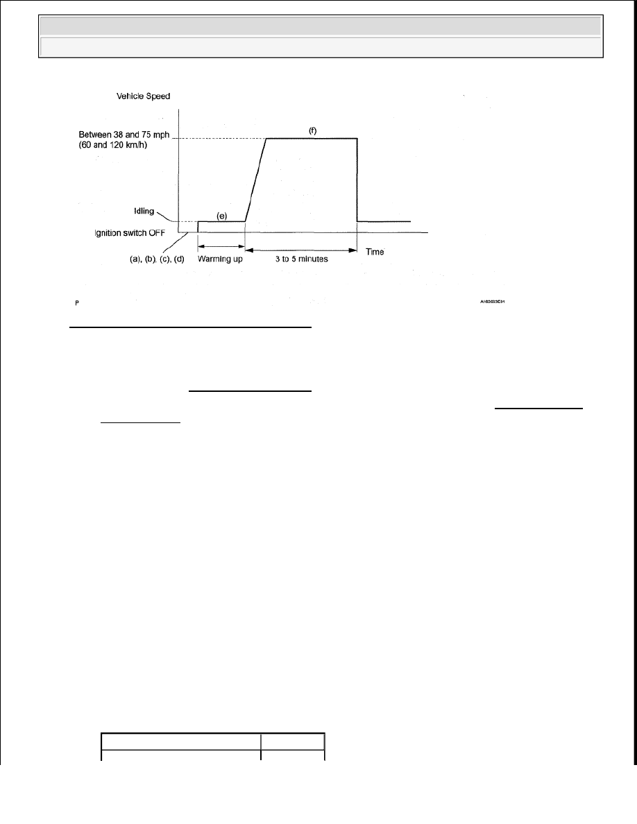


Fig. 92: Confirmation Driving Pattern Graph 

a. Connect the Techstream to the DLC3.  

b. Turn the ignition switch ON and turn the Techstream ON.  

c. Clear DTCs (See DTC CHECK/CLEAR ).  

d. Switch the ECM from normal mode to check mode using the Techstream (See CHECK MODE 

PROCEDURE ).  

e. Start the engine and warm it up with all the accessories switched OFF.  

f. Drive the vehicle at between 38 mph and 75 mph (60 km/h and 120 km/h) and at an engine speed 

of between 1400 RPM and 3200 RPM for 3 to 5 minutes. 

HINT: 

If the system is still malfunctioning, the MIL will be illuminated during step (f). 

16. CHECK WHETHER DTC OUTPUT RECURS (DTC P0171, P0172, P0174 OR P0175) 

a. Connect the Techstream to the DLC3.  

b. Turn the ignition switch ON and turn the Techstream ON.  

c. Enter the following menus: Powertrain/Engine and ECT/Trouble Codes.  

d. Read the DTCS. 

Result  

RESULT CHART 

NOTE:

If the conditions in this test are not strictly followed, no malfunction 
will be detected.

Display (DTC Output)

Proceed To


2008 Toyota Tundra 

2008 ENGINE PERFORMANCE Engine Control System (1GR-FE) - Tundra


B : REPLACE ECM (See REMOVAL ) 

A : END  

DTC P0230 FUEL PUMP PRIMARY CIRCUIT 

DESCRIPTION 

When a malfunction in the fuel pump circuit is detected, DTC P0230 is set. 

The fuel pump circuit consists of the ECM, fuel pump and fuel pump ECU (which operates the fuel pump). 
Based on the engine output, the ECM determines the fuel pump speed. The speed is then converted to a duty 
signal and sent to the fuel pump ECU. Based on the signal sent from the ECM, the fuel pump ECU adjusts the 
fuel pump operation speed between 3 settings. The fuel pump ECU also has a self-diagnosis function. Based on 
the fuel pump circuit condition, the fuel pump ECU outputs a diagnostic signal (Dl) to the ECM, and the ECM 
determines if there is a malfunction in the fuel pump circuit. 

DTC TROUBLE DETECTION CONDITION CHART 

MONITOR DESCRIPTION 

To monitor the fuel pump circuit, the ECM checks the fuel pump control signal (FPC) and diagnostic signal 
(Dl). The FPC voltage varies between approximately 0 V to approximately 12 V (duty signal). Based on the 
condition of the fuel pump ECU malfunction, the Dl voltage varies between approximately 0 V and 
approximately 12 V. The ECM then compares the variance of the FPC voltage and Dl voltage, and determines if 
the fuel pump circuit is malfunctioning. When the ECM determines that the fuel pump circuit is malfunctioning, 
a DTC is set immediately. 

WIRING DIAGRAM 

No Output

A

P0171, P0172, P0174 or P0175

B

DTC 

No.

DTC Detection Condition

Trouble Area

P0230

When either condition below is met: (1 trip detection 
logic) 

When fuel pump is operating: 

Remaining fuel is 17 L or more  

DI terminal output is low  

When fuel pump is not operating: 

DI terminal output is high  

Open or short in fuel pump 
circuit  

Fuel pump  

Fuel pump ECU  

ECM  


2008 Toyota Tundra 

2008 ENGINE PERFORMANCE Engine Control System (1GR-FE) - Tundra


Fig. 93: Fuel Pump Primary Wiring Diagram 

INSPECTION PROCEDURE 

This troubleshooting procedure is based on the premise that the engine is started. If the engine is not started, 
proceed to the problem symptoms table (See PROBLEM SYMPTOMS TABLE ). 

1. CHECK DTC OUTPUT 

a. Connect the Techstream to the DLC3.  

b. Turn the ignition switch ON.  

c. Enter the following menus: Body Electrical/Combination Meter/Trouble Codes.  

d. Read the DTC 

Result  


2008 Toyota Tundra 

2008 ENGINE PERFORMANCE Engine Control System (1GR-FE) - Tundra


RESULT CHART 

B : GO TO DTC B1500 . (See DTC B1500 FUEL SENDER OPEN DETECTED ). 

A : Go to next step  

2. PERFORM ACTIVE TEST USING TECHSTREAM 

a. Connect the Techstream to the DLC3.  

b. Turn the ignition switch ON and turn the Techstream ON.  

c. Enter the following menus: Powertrain/Engine and ECT/Active Test/Control the fuel pump/Speed.  

d. Check whether operating sounds can be heard while operating the relay using the Techstream. 

OK: Operating sounds can be heard from relay.  

NG : Go to step 7 

OK : Go to next step  

3. CHECK HARNESS AND CONNECTOR (FUEL PUMP ECU - ECM, BODY GROUND) 

a. Disconnect the R7 fuel pump ECU connector.  

b. Disconnect the A24 ECM connector.  

c. Measure the resistance according to the value(s) in the table below. 

Standard resistance (Check for open)  

TESTER CONNECTION SPECIFIED CONDITION 

Standard resistance (Check for short)  

TESTER CONNECTION SPECIFIED CONDITION 

NG : REPAIR OR REPLACE HARNESS OR CONNECTOR  

Result

Proceed To

DTC B1500 is not output A
DTC B1500 is output

B

Tester Connection

Condition Specified Condition

R7-1 (FPC) - A24-52 (FPC) Always

Below 1 ohms

R7-2 (DI) - A24-18 (DI)

Always

Below 1 ohms

R7-3 (E) - Body ground

Always

Below 1 ohms

Tester Connection

Condition Specified Condition

R7-1 (FPC) or A24-52 (FPC) - Body ground Always

10 kohms or higher

R7-2 (DI) or A24-18 (DI) - Body ground

Always

10 kohms or higher


2008 Toyota Tundra 

2008 ENGINE PERFORMANCE Engine Control System (1GR-FE) - Tundra


Content   ..  1182  1183  1184  1185   ..