Toyota Tundra. Manual - part 1182


  Index      Toyota     Toyota Tundra (2007-2010 year) - Service and Repair Manual


Search            copyright infringement  


Content   ..  1180  1181  1182  1183   ..


Toyota Tundra. Manual - part 1182
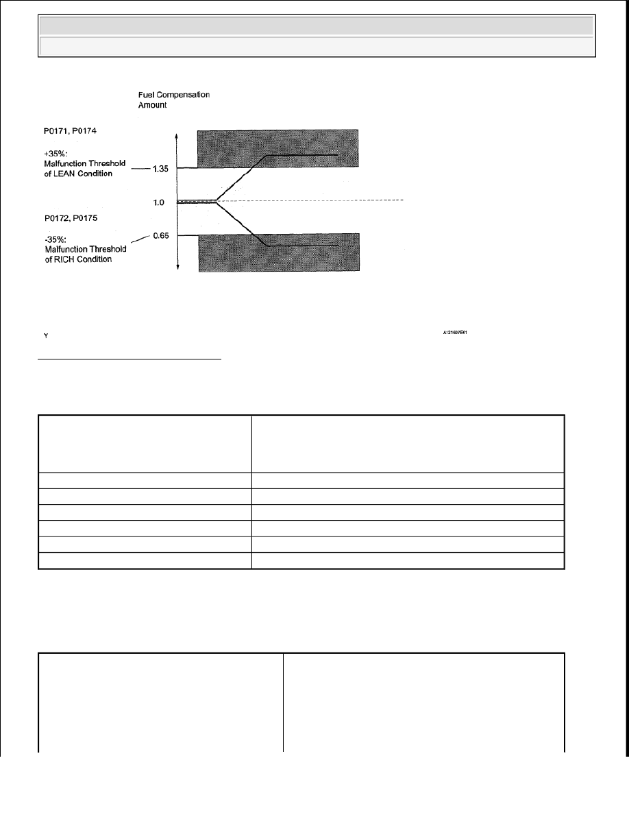


Fig. 91: Diagnosis For Fuel System 

MONITOR STRATEGY 

MONITOR STRATEGY 

TYPICAL ENABLING CONDITIONS 

Fuel-trim:  

TYPICAL ENABLING CONDITIONS 

Related DTCs

P0171: Fuel trim Lean (bank 1) 
P0172: Fuel trim Rich (bank 1) 
P0174: Fuel trim Lean (bank 2) 
P0175: Fuel trim Rich (bank 2)

Required Sensors/Components (Main)

Fuel system

Required Sensors/Components (Related)

A/F sensor. Mass air flow meter, Crankshaft position sensor

Frequency of Operation

Continuous

Duration

Within 10 seconds

MIL Operation

2 driving cycles

Sequence of Operation

None

P0010, P0020 (OCV Bank 1, 2) 
P0011 (VVT System 1 - Advance) 
P0012 (VVT System 1 - Retard) 
P0021 (VVT System 2 - Advance) 
P0022 (VVT System 2 - Retard) 
P0031, P0032, P0051, P0052 (A/F sensor heater - 


2008 Toyota Tundra 

2008 ENGINE PERFORMANCE Engine Control System (1GR-FE) - Tundra


TYPICAL MALFUNCTION THRESHOLDS 

Fuel-trim:  

TYPICAL MALFUNCTION THRESHOLDS 

WIRING DIAGRAM 

Refer to DTC P2195 . 

INSPECTION PROCEDURE 

HINT: 

Malfunctioning areas can be identified by performing the Control the Injection Volume for A/F sensor function 
provided in the Active Test. The Control the Injection Volume for A/F sensor function can help to determine 
whether the Air-Fuel Ratio (A/F) sensor, Heated Oxygen (HO2) sensor and other potential trouble areas are 
malfunctioning. 

The following instructions describe how to conduct the Control the Injection Volume for A/F sensor operation 
using the Techstream. 

1. Connect the Techstream to the DLC3.  

2. Start the engine and turn the Techstream ON.  

3. Warm up the engine at an engine speed of 2500 RPM for approximately 90 seconds.  

Monitor runs whenever following DTCs not 
present

Sensor 1) 
P0102 - P0103 (MAF meter) 
P0115 - P0118 (ECT sensor) 
P0120 - P0223, P2135 (TP sensor) 
P0125 (Insufficient ECT for closed loop) 
P0335 (CKP sensor) 
P0340 (VVT sensor) 
P0351 - P0356 (Igniter) 
P0500 (VSS)

Fuel system status

Closed-loop

Battery voltage

11 V or more

Either of following conditions 1 or 2 set

-

1. Engine RPM

Below 1100 RPM

2. Intake air amount per revolution

0.22 g/rev or more

Catalyst monitor

No executed

Purge-cut

Executing

Either of following conditions 1 or 2 met

-

1. Average between short-term fuel trim and long-term fuel trim

35% or more (varies with ECT)

2. Average between short-term fuel trim and long-term fuel trim

-35% or less (varies with ECT)


2008 Toyota Tundra 

2008 ENGINE PERFORMANCE Engine Control System (1GR-FE) - Tundra


4. Enter the following menus: Powertrain/Engine and ECT/Active Test/Control the Injection Volume for 

A/F sensor.  

5. Perform the Active Test operation with the engine in an idling condition (press the RIGHT or LEFT 

button to change the fuel injection volume.)  

6. Monitor the output voltages of the A/F and HO2 sensors (AFS B1 S1 and O2S B1 S2 or AFS B2 S1 and 

O2S B2 S2) displayed on the Techstream.  

HINT: 

The Control the Injection Volume for A/F sensor operation lowers the fuel injection volume by 12.5% or 
increases the injection volume by 25%.  

Each sensor reacts in accordance with increases and decreases in the fuel injection volume.  

VOLTAGE REFERENCE 

VOLTAGE REFERENCE 

Tester Display (Sensor)

Injection Volume

Status

Voltage

AFS B1 S1 or AFS B2 S1 (A/F)

+25%

Rich

Less than 3.0 V

AFS B1 S1 or AFS B2 S1 (A/F)

-12.5%

Lean

More than 3.35 V

O2S B1 S2 or O2S B2 S2 (HO2)

+25%

Rich

More than 0.55 V

O2S B1 S2 or O2S B2 S2 (HO2)

-12.5%

Lean

Less than 0.4 V

NOTE:

The Air-Fuel Ratio (A/F) sensor has an output delay of a few seconds and the 
Heated Oxygen (HO2) sensor has a maximum output delay of approximately 20 
seconds.

Case

A/F Sensor (Sensor 1) Output 

Voltage

HO2 Sensor (Sensor 2) 

Output Voltage

Main Suspected Trouble Area

1

-

2

A/F sensor  

A/F sensor heater  

A/F sensor circuit  

3

HO2 sensor  

HO2 sensor heater  

HO2 sensor circuit  

4

Injector  

Fuel pressure  

Gas leakage from exhaust 
system (Air-fuel ratio 


2008 Toyota Tundra 

2008 ENGINE PERFORMANCE Engine Control System (1GR-FE) - Tundra


Following the Control the Injection Volume for A/F sensor procedure enables technicians to check and 
graph the voltage outputs of both the A/F and HO2 sensors.  

To display the graph, enter the following menus: Powertrain/Engine and ECT/Active Test/Control the 
Injection Volume for A/F Sensor/A/F Control System/AFS B1 S1 and O2S B1 S2 or AFS B2 S1 and O2S 
B2 S2.  

HINT: 

Read freeze frame data using the Techstream. Freeze frame data records the engine condition when 
malfunctions are detected. When troubleshooting, freeze frame data can help determine if the vehicle was 
moving or stationary, if the engine was warmed up or not, if the air-fuel ratio was lean or rich, and other 
data from the time the malfunction occurred.  

A low A/F sensor voltage could be caused by a rich air-fuel mixture. Check for conditions that would 
cause the engine to run rich.  

A high A/F sensor voltage could be caused by a lean air-fuel mixture. Check for conditions that would 
cause the engine to run lean.  

1. CHECK ANY OTHER DTCS OUTPUT (IN ADDITION TO DTC P0171, P0172, P0174 OR P0175) 

a. Connect the Techstream to the DLC3.  

b. Turn the ignition switch ON and turn the Techstream ON.  

c. Enter the following menus: Powertrain/Engine and ECT/Trouble Codes.  

d. Read the DTCs. 

Result  

RESULT CHART 

HINT: 

If any DTCs other than P0171, P0172, P0174 or P0175 are output, troubleshoot those DTCs first. 

B : GO TO DTC CHART (See DIAGNOSTIC TROUBLE CODE CHART ) 

A : Go to next step  

2. CHECK PCV HOSE CONNECTIONS 

OK: PCV hose is connected correctly and is not damaged.  

NG : REPAIR OR REPLACE PCV HOSE  

extremely rich or lean)  

Display (DTC Output)

Proceed To

P0171, P0172, P0174 or P0175

A

P0171, P0172, P0174 or P0175 and other DTCs

B


2008 Toyota Tundra 

2008 ENGINE PERFORMANCE Engine Control System (1GR-FE) - Tundra


Content   ..  1180  1181  1182  1183   ..