Toyota Tundra. Manual - part 3


  Index      Toyota     Toyota Tundra (2007-2010 year) - Service and Repair Manual


Search            copyright infringement  


Content   ..  1  2  3  4  ..


Toyota Tundra. Manual - part 3


h. CLAWS 

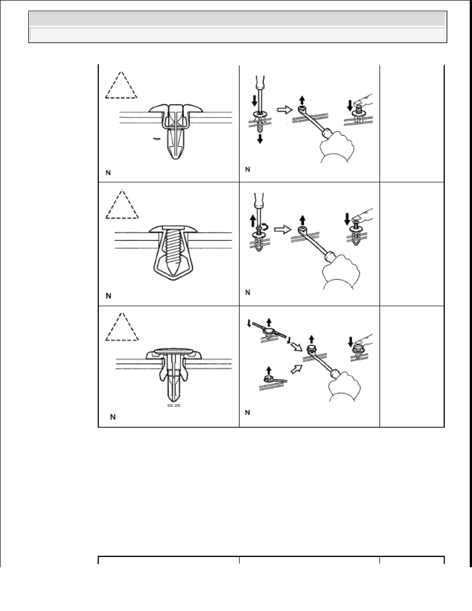
1. The removal and installation methods of typical claws used for vehicle body parts are shown 

in the table below. 

HINT: 

If claws of caps or covers are damaged during a procedure, always replace the caps or covers 
with new ones. 

REMOVAL AND INSTALLATION METHODS OF TYPICAL CLAWS FOR 
VEHICLE BODY PARTS
 

Remove clips by 
pushing the 
center pin 
through and 
prying out the 
shell.

Remove clips by 
unscrewing the 
center pin and 
prying out the 
shell.

Remove clips by 
prying out the 
pin and then 
prying out the 
shell.


2009 Toyota Tundra 

2009 GENERAL INFORMATION Introduction - Tundra


i. REMOVAL AND INSTALLATION OF VACUUM HOSES 

1. To disconnect a vacuum hose, pull and twist from the end of the hose. Do not pull from the 

middle of the hose as this may cause damage. 

Fig. 10: Identifying Correct & Incorrect Method Of Disconnecting Vacuum Hose 
Courtesy of TOYOTA MOTOR SALES, U.S.A., INC. 

Shape (Example)

Graphic

Procedures

Using a 
screwdriver, 
detach the claws 
and remove the 
caps or covers.

Using a 
screwdriver, 
detach the claws 
and remove the 
caps or covers.

Using a 
screwdriver, 
detach the claws 
and remove the 
caps or covers.


2009 Toyota Tundra 

2009 GENERAL INFORMATION Introduction - Tundra


2. When disconnecting vacuum hoses, use tags to identify where they should be reconnected.  

3. After completing any hose related repairs, double check that the vacuum hoses are properly 

connected. The label under the hood shows the proper layout.  

4. When using a vacuum gauge, never force the hose onto a connector that is too large. If a hose 

has been stretched, it may leak air. Use a step-down adapter if necessary. 

Fig. 11: Identifying Tags On Replacement Parts 
Courtesy of TOYOTA MOTOR SALES, U.S.A., INC. 

j. TORQUE WHEN USING TORQUE WRENCH WITH EXTENSION TOOL 

Fig. 12: Identifying Length Of Extension Tool & Torque Wrench 
Courtesy of TOYOTA MOTOR SALES, U.S.A., INC. 

1. Use the formula below to calculate special torque values for situations where SST or an 

extension tool is combined with a torque wrench. 

Fig. 13: Identifying Length Of SST & Torque Wrench 
Courtesy of TOYOTA MOTOR SALES, U.S.A., INC. 


2009 Toyota Tundra 

2009 GENERAL INFORMATION Introduction - Tundra


Formula:  

T' = L2/(L1 + L2) * T  

FORMULA DESCRIPTION CHART 

2. FOR VEHICLES WITH SUPPLEMENTAL RESTRAINT SYSTEM 

The TOYOTA TUNDRA is equipped with a Supplemental Restraint System (SRS). The SRS of this 
vehicle consists of the following: 

1. Steering pad  

2. Front passenger airbag assembly  

3. Curtain shield airbag assembly  

4. Front seat side airbag assembly  

5. Center airbag sensor assembly  

6. Front airbag sensor  

7. Side airbag sensor  

8. Seat position airbag sensor  

9. Door side airbag sensor  

10. Occupant classification ECU  

11. Front seat outer belt assembly with pretensioner 

T' Reading of torque wrench {N*m (kgf*cm, ft.*lbf)}
T Torque {N*m (kgf*cm, ft.*lbf)}
L1 Length of SST or extension tool {cm, (in.)}
L2 Length of torque wrench {cm (in.)}

NOTE:

If an extension tool or SST is combined with a torque wrench 
and the wrench is used to tighten to a torque specification in 
this article, the actual torque will be excessive and parts will be 
damaged.

CAUTION:

Failure to carry out service procedures in the correct 
sequence could cause SRS parts to unexpectedly deploy 
and possibly lead to serious injuries. Furthermore, if a 
mistake is made when servicing SRS parts, they may fail to 
operate when required. Before performing servicing 
(including installation/removal, inspection and 
replacement of parts), be sure to read the following 
precautions.  

Before starting work, wait at least 90 seconds after the 
ignition switch is turned OFF and after the cable of the 
negative (-) battery terminal is disconnected. (SRS parts 


2009 Toyota Tundra 

2009 GENERAL INFORMATION Introduction - Tundra


Content   ..  1  2  3  4  ..