Suzuki Grand Vitara JB416 / JB420 / JB419. Manual - part 410
 

  Index      Suzuki     Suzuki Grand Vitara JB416 / JB420 / JB419 - service repair manual 2007 year


Search            


Content   ..  408  409  410  411   ..


Suzuki Grand Vitara JB416 / JB420 / JB419. Manual - part 410


8B-25 Air Bag System: 

DTC B1016: Power Source Voltage High

S6JB0A8204012

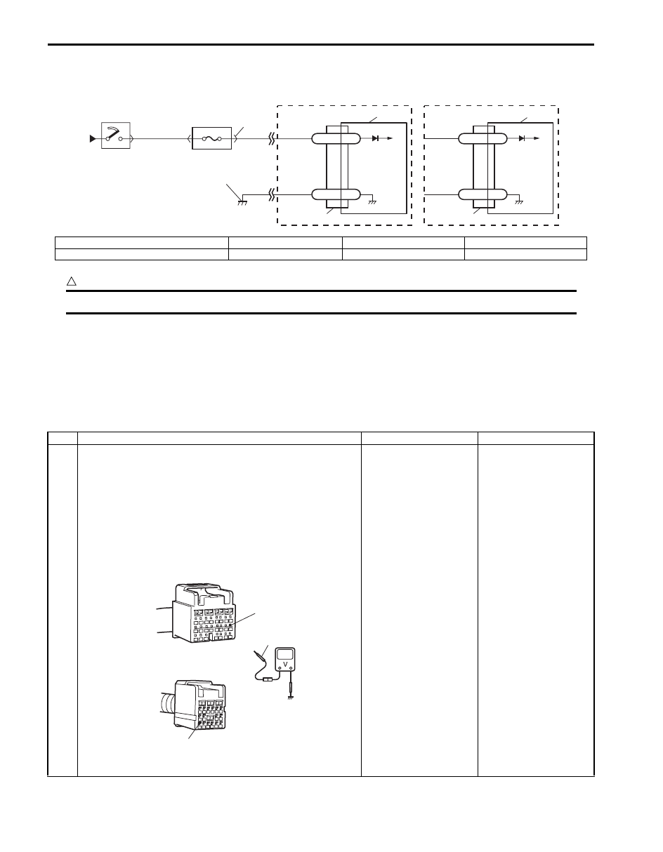
Wiring Diagram

CAUTION

!


Be sure to observe instructions under CAUTION in “Air Bag Diagnostic System Check Flow”.


DTC Will Set when
The power source voltage to SDM is above specified value for specified time.

Flow Test Description
Step 1: Check if voltage applied to SDM is within normal range.
Step 2: Check if DTC B1016 still exists.

DTC Troubleshooting

BLK

G47-20 GND

“G47”

1

2

4

3

RED

BLK

RED

BLK/YEL

“G01”

G47-16

IG

[A]

G46-16 GND

“G46”

G46-11

IG

[B]

6

5

5

I5JB0A820022-01

[A]: Without side-air bag and curtain air bag

1. From main fuse

3. “A/B” fuse

5. SDM

[B]: With side-air bag and curtain air bag

2. Ignition switch

4. Junction block assembly

6. Ground for air bag system

Step

Action

Yes

No

1

1) With ignition switch OFF, disconnect SDM connector.
2) Check proper connection to SDM at “G47-16” or “G46-

11” terminal.

3) If OK, turn ignition switch ON and then check voltage 

between “G47-16” [A] or “G46-11” [B] terminal on SDM 
connector and body ground.

Special tool
(A):  09932–76010

Is voltage 14 V or less?

Go to Step 2.

Check charging system 
and repair as necessary 
referring to “Generator 
Test (Overcharged 
Battery Check): For 
Petrol Engine Model in 
Section 1J”
 or 
“Generator Test 
(Overcharged Battery 
Check): For Diesel 
Engine Model in Section 
1J”.

(A)

[A]

[B]

“G46-11”

“G47-16”

I5JB0A820023-01

Air Bag System:  8B-26

NOTE
Upon completion of inspection and repair work, perform the following items.
• Reconnect all air bag system components and ensure all components are properly mounted.
• Clear DTCs referring to “DTC Clearance”, if any
.
• Repeat “Air Bag Diagnostic System Check” 
to confirm that the trouble has been corrected.


DTC B1017: Power Source Voltage Low

S6JB0A8204013

Wiring Diagram
Refer to “DTC B1016: Power Source Voltage High”.

CAUTION

!


Be sure to observe instructions under CAUTION in “Air Bag Diagnostic System Check Flow”.


DTC Will Set when
The power source voltage is below specified value for specified time.

Flow Test Description
Step 1: Check if voltage on battery is within normal range.
Step 2: Check if voltage applied to SDM is within normal range.
Step 3: Check if voltage applied to “L04” connector is within normal range.
Step 4: Check if DTC B1017 still exists.

DTC Troubleshooting

2

1) With ignition switch OFF, reconnect SDM connector.

With ignition switch ON, is DTC B1016 indicated?

Substitute a known-
good SDM and recheck.

Intermittent trouble. 
Check for intermittent 
trouble referring to 
“Inspection of 
Intermittent and Poor 
Connections” I
f OK, 
substitute a known-
good SDM and recheck.

Step

Action

Yes

No

Step

Action

Yes

No

1

1) Measure voltage on battery.

Is voltage 11 V or more?

Go to Step 2.

Check charging system 
and repair as necessary 
referring to “Generator 
Test (Undercharged 
Battery Check): For 
Petrol Engine Model in 
Section 1J” 
or 
“Generator Test 
(Undercharged Battery 
Check): For Diesel 
Engine Model in Section 
1J”.

8B-27 Air Bag System: 

2

1) With ignition switch OFF, disconnect SDM connector.
2) Check proper connection to SDM at “G47-16” or “G46-

11” terminal.

3) If OK, turn ignition switch ON and then check voltage 

between “G47-16” [A] or “G46-11” [B] terminal on SDM 
connector and body ground.

Special tool
(A):  09932–76010 

Is voltage 8 V or more?

Go to Step 4.

Go to Step 3.

3

1) With ignition switch OFF, disconnect on connector “G01” 

junction block assembly.

2) Check proper connection at “G01-15” terminal.
3) If OK, turn ignition switch ON and then check voltage 

between “G01-15” terminal and body ground.

Is voltage 8 V or more?

Go to Step 4.

Check circuit from 
battery to “G01” 
connector and charging 
system.

Step

Action

Yes

No

(A)

[A]

[B]

“G46-11”

“G47-16”

I5JB0A820023-01

“G01-15”

I5JB0A820024-01

Air Bag System:  8B-28

NOTE
Upon completion of inspection and repair work, perform the following items.
• Reconnect all air bag system components and ensure all components are properly mounted.
• Clear DTCs referring to “DTC Clearance”, if any
.
• Repeat “Air Bag Diagnostic System Check” 
to confirm that the trouble has been corrected.


DTC B1021: Air Bag Module Deployed

S6JB0A8204014

DTC Will Set when
The SDM detects a crash of sufficient force to warrant activation of the air bag system. (SDM outputs a deployment 
command.)

Flow Test Description
Step 1: Check that DTC B1021 has been set although air bag has not been deployed.
Step 2: Check that DTC has been set due to failure of SDM.

NOTE
Before executing items in this flow, be sure to perform “Air Bag Diagnostic System Check”.


DTC Troubleshooting

NOTE
Upon completion of inspection and repair work, perform the following items.
• Reconnect all air bag system components and ensure all components are properly mounted.
• Repeat “Air Bag Diagnostic System Check” 
to confirm that the trouble has been corrected.
• Clear DTCs of BCM referring to “DTC Clearance in Section 10B”.


4

1) With ignition switch OFF, reconnect SDM connector.

With ignition switch ON, does DTC B1017 exist?

Substitute a known-
good SDM and recheck.

Check charging system 
and repair as necessary 
referring to “Generator 
Test (Undercharged 
Battery Check): For 
Petrol Engine Model in 
Section 1J” 
or 
“Generator Test 
(Undercharged Battery 
Check): For Diesel 
Engine Model in Section 
1J”.

Step

Action

Yes

No

Step

Action

Yes

No

1

1) Turn ignition switch OFF.

Has air bag deployed?

Replace components 
and perform inspections 
as directed in “Repair 
and Inspection 
Required after 
Accident”
.

Go to Step 2.

2

1) Inspect front of vehicle and undercarriage for signs of 

impact.

Are there signs of impact?

Replace components 
and perform inspections 
as directed in “Repair 
and Inspection 
Required after 
Accident”
.

Substitute a known-
good SDM and recheck.


Content   ..  408  409  410  411   ..