Suzuki Grand Vitara JB416 / JB420 / JB419. Manual - part 388
7B-43 Air Conditioning System:
DTC B1512: Air Flow Control Actuator (Position Sensor) and/or Its Circuit Malfunction
S6JB0A7204016
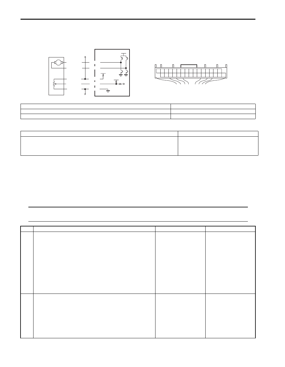
Wiring Diagram
DTC Detecting Condition and Trouble Area
DTC Confirmation Procedure
1) Connect scan tool to DLC with ignition switch turned OFF.
2) Turn ON ignition switch and clear DTC using scan tool.
3) Check DTC.
DTC Troubleshooting
NOTE
When DTC B1502, B1503, B1511 and B1530 are indicated together, it is possible that “BLK/RED” wire
circuit open.
12V
5V
M
5V
G52-23
G52-29
G52-30
G52-13
GRY/RED
GRY/BLK
RED/WHT
WHT/BLU
BLK/RED
G52-14
[A]
2
3
4
1
13
14
30 29
23
I5JB0A720024-02
[A]: HVAC control unit connector “G52” (harness side view)
3. To other actuators
1. HVAC control module
4. To other sensors
2. Air flow control actuator
DTC Detecting Condition
Trouble Area
Air flow control actuator position sensor signal voltage is more than or less
than specified value for specified time continuously.
• Air flow control actuator circuit
• Air flow control actuator
• HVAC control module
Step
Action
Yes
No
1
Position sensor power supply circuit check
1) Disconnect air flow control actuator connector with
ignition switch turned OFF.
2) Check for proper connection to air flow control actuator
at “RED/WHT”, “WHT/BLU” and “BLK/RED” wire
terminals.
3) If OK, measure voltage between “RED/WHT” wire
terminal of air flow control actuator connector and
vehicle body ground with ignition switch turned ON.
Is voltage 4 – 6 V?
Go to Step 6.
Go to Step 2.
2
Position sensor power supply circuit check
1) Disconnect temperature control actuator connector with
ignition switch turned OFF.
2) Measure voltage between “RED/WHT” wire terminal of
air flow control actuator connector and vehicle body
ground with ignition switch turned ON.
Is voltage 4 – 6 V?
Temperature control
actuator faulty.
Go to Step 3.