Suzuki Grand Vitara JB416 / JB420 / JB419. Manual - part 368
 

  Index      Suzuki     Suzuki Grand Vitara JB416 / JB420 / JB419 - service repair manual 2007 year


Search            


Content   ..  366  367  368  369   ..


Suzuki Grand Vitara JB416 / JB420 / JB419. Manual - part 368


6C-15 Power Assisted Steering System: 

Installation
Reverse removal procedure for installation of P/S gear 
case, noting the following points.
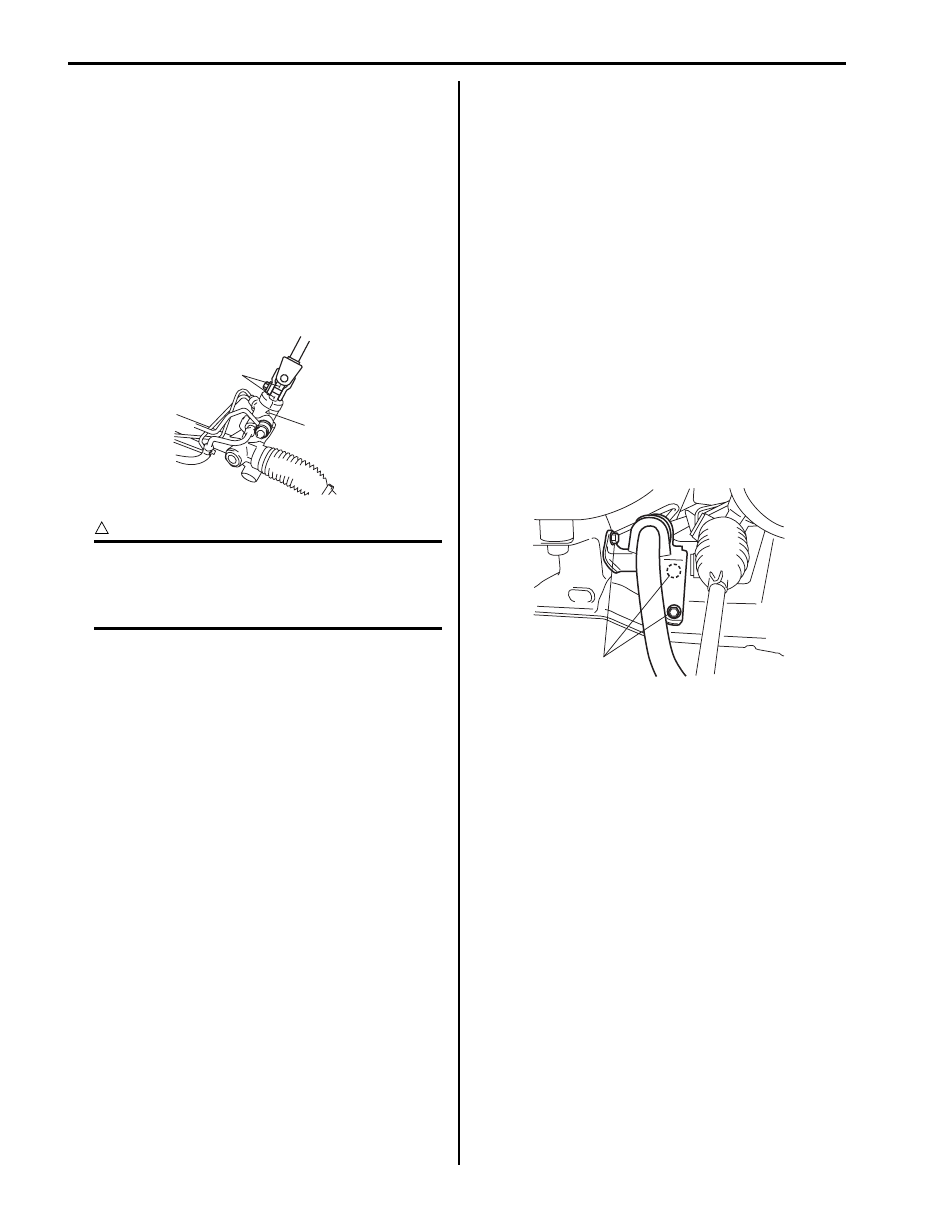
• After confirming that front tire is in straight position, 

install P/S gear case to body temporarily. Next, with 
tie-rod end installed to knuckle, set rack in position 
close to neutral. Then obtain the neutral state by 
aligning match marks (1) on pinion shaft and steering 
gear case (2) and insert steering lower joint into pinion 
shaft.
Refer to Step 3) of “Installation” in “Steering Lower 
Shaft Assembly Removal and Installation in Section 
6B”.

CAUTION

!


Be sure to confirm that steering wheel and 
front tires (wheels) are in straight position 
when inserting steering lower joint into 
steering pinion shaft.


• If a plug was put to disconnected pipe when removing 

steering gear case, remove that plug before 
reconnecting pipe.

• Use specified torque as given below.

Tightening torque
Steering lower shaft bolt:  25 N·m (2.5 kgf-m, 18.5 
lb-ft)
Gear case high pressure pipe union bolt:  35 N·m 
(3.5 kgf-m, 25.5 lb-ft)
Gear case cylinder pipe flare nut:  25 N·m (2.5 kgf-
m, 18.0 lb-ft)
Gear case mounting bolt:  105 N·m (10.5 kgf-m, 76 
lb-ft)
Gear case low pressure pipe union bolt:  40 N·m (
4.0 kgf-m, 29.0 lb-ft)
Stabilizer bar mount bracket mount bolt (a):  60 
N·m (6.0 kgf-m, 43.0 lb-ft)
Gear case low pressure pipe flare nut:  35 N·m (
3.5 kgf-m, 25.5 lb-ft) (F9Q engine model)
P/S pump bracket bolt:  55 N·m (5.5 kgf-m, 40.0 lb-
ft) (F9Q engine model)

• After installation, be sure to fill specified P/S fluid and 

bleed air. Refer to “P/S System Air Bleeding 
Procedure”
.

• Check toe setting. Adjust as required. Refer to “Front 

Wheel Alignment Inspection and Adjustment in 
Section 2B”.

2

1

I5JB0A630020-01

(a)

I5JB0A630021-02

Power Assisted Steering System:  6C-16

Steering Gear Case Mount Bushing Removal 
and Installation

S6JB0A6306015

Removal

1) Remove P/S gear case assembly referring to “P/S 

Gear Case Assembly Removal and Installation”.

2) Push out bushing using hydraulic press (1) and 

special tools.

Special tool
(A):  09943–88211
(B):  09945–55410

Installation

CAUTION

!


Be sure to use new bushing.


1) Press-fit bushing (1) using special tools and press 

(2).

Special tool
(A):  09913–75821
(B):  09945–55410

NOTE
Before installing bushing, apply soap water 
on its circumference to facilitate installation.


2) Press-fit bushing (1) so that dimensions and in figure 

become equal.

3) Install P/S gear case assembly referring to “P/S 

Gear Case Assembly Removal and Installation”.

Steering Gear Case Mount Bushing Inspection

S6JB0A6306016

Inspect for looseness, cracks, deformation or damage. 
Replace any defective part.

Rack Boot / Tie-Rod Removal and Installation

S6JB0A6306017

Removal

1) Remove P/S gear case assembly, referring to “P/S 

Gear Case Assembly Removal and Installation”.

2) For ease of adjustment after installation, make 

marking (4) of tie-rod end lock nut position of tie-rod 
thread.

3) Loosen tie-rod end lock nut (2) and remove tie-rod 

end.

4) Remove boot wire and clip.
5) Remove boot (3) from tie-rod (1).

(A)

1

(B)

I5JB0A630053-02

(A)

2

(B)

I5JB0A630055-01

“A”: 6 mm (0.24 in.)

“B”: 80 mm (3.15 in.)

1

1

“B”

“A”

“A”

I5JB0A630056-01

I5JB0A630054-01

6C-17 Power Assisted Steering System: 

6) Remove tie-rod (1) from steering gear case (2).

Installation

1) Clean threads of both tie-rod and steering gear case 

(2).

2) Apply thread lock cement to thread of tie-rod ball nut 

(1) and then tighten it to specified torque.

“B”:  Thread lock cement 99000–32100 (Thread 
Lock Cement 1305)

Tightening torque
Tie-rod ball nut (a):  90 N·m (9.0 kgf-m, 65.0 lb-ft)

3) Apply grease to boot inside “A” indicated in the 

figure.

4) Position boot properly in grooves of gear case and 

tie-rod. Check to ensure that boot is free from twist 
and dent.

5) Clamp boot with clip and wire. Wire should be new 

and should go around the boot twice.
Pull its both ends together by screwdriver or such 
and make sure that the wire won’t be crossed. Then 
twist the ends several times, the twisted ends should 
be bent in the circumferential direction.

6) Install tie-rod end lock nut and tie-rod end to tie-rod. 

Position lock nut to marking (1) made in removal.

NOTE
When tie-rod was replaced, measure length 
“a” on removed tie-rod and use it on new 
replacement tie-rod so as to position lock nut 
properly.


7) Install steering gear case. Refer to “P/S Gear Case 

Assembly Removal and Installation”.

3. Aluminium plate

4. Vise

3

1

4

2

3

I5JB0A630022-01

2

1, (a), “B”

I5JB0A630023-03

IYSQ01630030-01

IYSQ01630035-01

I5JB0A630058-01

Power Assisted Steering System:  6C-18

P/S Hose / Pipe Components

S6JB0A6306018

[A]

[B]

7

1

6

4

2

11

9

3

5

6

6

(b)

13

13

13

1

10

(a)

15

(a)

14

(a)

(c)

10

(c)

12

(c)

12

(c)

13

8

8

7

5

2

8

8

3

6

4

9

6

6

11

(a)

15

(a)

14

(a)

(b)

I6JB0A630004-02


Content   ..  366  367  368  369   ..