Suzuki Grand Vitara JB416 / JB420 / JB419. Manual - part 366
 

  Index      Suzuki     Suzuki Grand Vitara JB416 / JB420 / JB419 - service repair manual 2007 year


Search            


Content   ..  364  365  366  367   ..


Suzuki Grand Vitara JB416 / JB420 / JB419. Manual - part 366


6C-7 Power Assisted Steering System: 

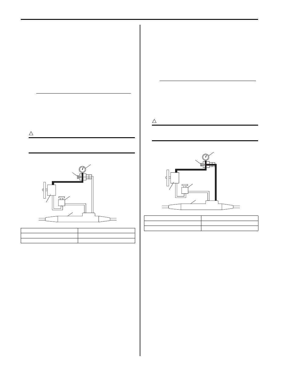
5) Check relief pressure.

a) Increase engine speed to about 600 r/min. (rpm). 

Close gauge valve gradually while watching 
pressure increase indicated by gauge and take 
reading of relief pressure (maximum hydraulic 
pressure).
If it is higher than specified values, possible 
cause is malfunction of relief valve.
If it is lower than specified values, possible 
cause is either failure of P/S pump or settling of 
relief valve spring.

Relief pressure when gauge value is closed
M16A Engine model: 6170 – 6870 kPa (61.7 – 
68.7 kg/cm

2

, 877 – 977 psi)

J20A Engine model: 6560 – 7360 kPa (65.6 – 
73.6 kg/cm

2

, 933 – 1047 psi)

F9Q Engine model: 7650 – 8340 kPa (77.3 – 
84.2 kg/cm

2

, 1099 – 1197 psi)

CAUTION

!


Be sure not to close gauge valve for longer 
than 10 seconds.


b) Open gauge valve fully and increase engine 

speed to about 1500 r/min. (rpm). Then turn 
steering wheel to the left or right fully and take 
reading of relief pressure.
If it is higher than specified values, possible 
cause is malfunction of relief valve.
If it is lower than specified values, possible 
cause is failure in steering gear case. Replace 
gear case.

Relief pressure when gauge value is opened
M16A Engine model: 6170 – 6870 kPa (61.7 – 
68.7 kg/cm

2

, 877 – 977 psi)

J20A Engine model: 6560 – 7360 kPa (65.6 – 
73.6 kg/cm

2

, 933 – 1047 psi)

F9Q Engine model: 7650 – 8340 kPa (77.3 – 
84.2 kg/cm

2

, 1099 – 1197 psi)

CAUTION

!


Be sure not to hold steering wheel at fully 
turned position for longer than 10 seconds.


1. P/S fluid reservoir

4. P/S pump

2. Gauge valve (shut)

5. P/S gear case

3. Oil pressure gauge

2

4

1

3

5

I5JB0A630009-04

1. P/S fluid reservoir

4. P/S pump

2. Gauge valve (open)

5. P/S gear case

3. Oil pressure gauge

2

4

1

3

5

I5JB0A630010-01

Power Assisted Steering System:  6C-8

Repair Instructions

P/S Fluid Change

S6JB0A6306001

CAUTION

!


Do not use any fluid other than the specified 
P/S fluid. Use of any fluid other than the 
specified P/S fluid may cause juddering or 
some other faulty condition to occur.


1) Lift up vehicle.
2) Remove front under cover.
3) When engine is cool, remove P/S gear low pressure 

hose (1) from pipe and drain P/S fluid from low 
pressure hose.

4) Install low pressure hose to pipe.
5) Fill specified P/S fluid and bleed air referring to “P/S 

System Air Bleeding Procedure”.

P/S fluid specification
: Equivalent of DEXRON

®

-II

P/S fluid capacity
Reference: 0.7 – 0.8 liters (1.48/1.23 – 1.69/1.41 
US/Imp.pt)

P/S Fluid Level Check

S6JB0A6306002

With engine stopped, check fluid level indicated on P/S 
fluid reservoir, which should be between “UPPER” and 
“LOWER” marks. If it is lower than “LOWER” mark, fill 
fluid up to “UPPER” mark.

NOTE

• Be sure to use an specified power steering 

fluid.

• Fluid level should be checked when fluid is 

cool.


1

I5JB0A630011-01

I5JB0A630012-01

6C-9 Power Assisted Steering System: 

P/S Fluid Leakage Check

S6JB0A6306003

Start engine and turn steering wheel fully to the right and left so that maximum hydraulic pressure is provided. 
Then visually check P/S gear case assembly (1), P/S pump (2) and P/S fluid reservoir (3) themselves and each joint of 
their connecting pipes for leakage.

CAUTION

!


Never keep steering wheel turned fully for longer than 10 seconds.


P/S System Air Bleeding Procedure

S6JB0A6306004

1) Hoist the front end of vehicle and apply safety stands.
2) Fill P/S fluid reservoir with fluid up to specified level.

NOTE
Before starting engine, place transmission gear shift lever in “Neutral” (shift selector lever to “P” 
range for A/T model), and set parking brake.


3) After running engine at idling speed for 3 to 5 seconds, stop it and add fluid to satisfy specification.
4) With engine stopped, turn steering wheel to the right and left as far as it stops, repeat it a few times and fill fluid to 

specified level.

5) With engine running at idling speed, repeat stop-to-stop turn of steering wheel till all foams in P/S fluid reservoir 

are gone.

NOTE
Make sure to bleed air completely. If air remains in fluid, P/S pump may make humming noise or 
steering wheel may feel heavy.


6) Finally check to make sure that fluid is filled to specified level.

[A]

[B]

2

3

1

2

3

1

I6JB0A630003-02

[A]: LH steering vehicle for J20A engine model
[B]: RH steering vehicle for J20A engine model

Power Assisted Steering System:  6C-10

P/S Pump and A/C Compressor (If Equipped) 
Drive Belt Inspection and Adjustment (M16A 
Engine Model)

S6JB0A6306005

Inspection
• Check that belt is free from any damage and properly 

fitted in pulley groove.

• Check belt tension by measuring how much it deflects 

when pushed at intermediate point between pulleys 
with about 10 kg (22 lb) force.

Deflection of P/S belt with A/C (a)
: 9 – 10 mm (0.35 – 0.39 in.)

Deflection of P/S belt without A/C (b)
: 4 – 9 mm (0.16 – 0.35 in.)

Adjustment

1) To adjust P/S belt tension, loosen tension pulley bolt 

(2) and nut (1) and turn tension pulley (3) using 
hexagon wrench (4).

2) Adjust belt tension to specification, and then tighten 

tension pulley bolt (2) and nut (1) to specified torque.

Tightening torque
P/S belt tension pulley bolt (a):  25 N·m (2.5 kgf-
m, 18.5 lb-ft)
P/S belt tension pulley nut (b):  25 N·m (2.5 kgf-
m, 18.5 lb-ft)

P/S Pump and A/C Compressor (If Equipped) 
Drive Belt Inspection and Adjustment (J20A 
Engine Model)

S6JB0A6306006

Refer to “Water Pump and Generator Drive Belt On-
Vehicle Inspection (For J20 Engine): For Petrol Engine 
Model in Section 1J”.

P/S Pump and A/C Compressor (If Equipped) 
Drive Belt Inspection (F9Q Engine Model)

S6JB0A6306026

Refer to “Accessory Drive Belt Inspection: For Diesel 
Engine Model in Section 1J”.

1. P/S pump pulley

5. Tension pulley bolt

2. A/C compressor pulley (A/C model)

6. Tension pulley nut

3. Crankshaft pulley

[A]: A/C model

4. Tension pulley

[B]: Non A/C model

4

5

6

4

3

3

2

1

1

[A]

[B]

“a”

“b”

5

6

I5JB0A630013-01

5. Loose

7. P/S pump pulley

6. Tight

8. Crank shaft pulley

4

8

3

7

6

1, (b)

2, (a)

5

I5JB0A630014-01


Content   ..  364  365  366  367   ..