Suzuki Grand Vitara JB416 / JB420 / JB419. Manual - part 364
 

  Index      Suzuki     Suzuki Grand Vitara JB416 / JB420 / JB419 - service repair manual 2007 year


Search            


Content   ..  362  363  364  365   ..


Suzuki Grand Vitara JB416 / JB420 / JB419. Manual - part 364


6B-14 Steering Wheel and Column: 

Steering Lower Shaft Assembly Removal and 
Installation

S6JB0A6206015

CAUTION

!


Never turn steering wheel while steering 
lower shaft assembly is removed.
Should it have been turned and contact coil 
cable assembly have got out of its centered 
position, it needs to be centered again. Also, 
turning steering wheel more than about two 
and a half turns will break contact coil cable 
assembly.


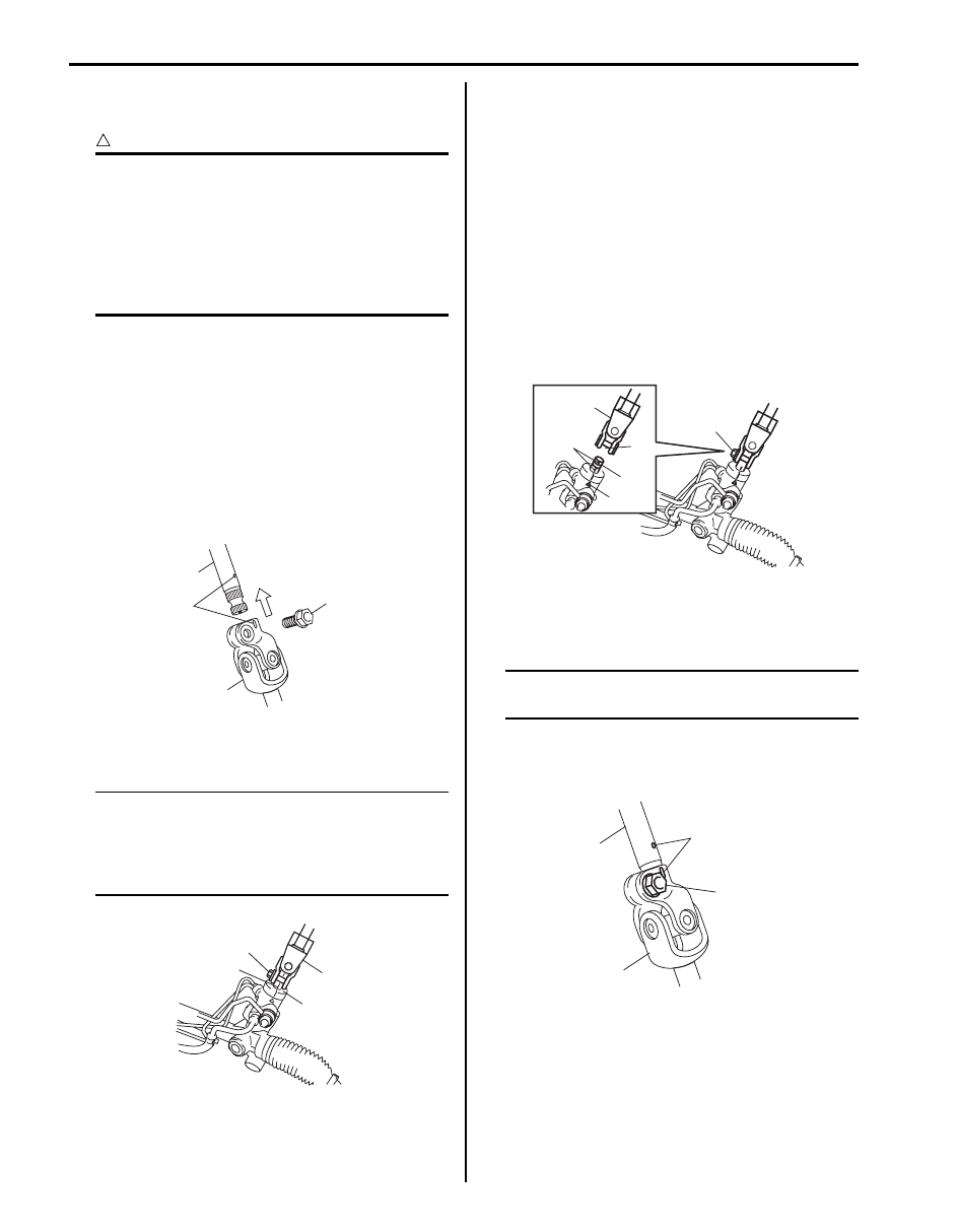
Removal

1) Turn steering wheel so that vehicle’s front tires are at 

straight-ahead position.

2) Turn ignition switch to LOCK position and remove 

key.

3) Make alignment marks (1) on steering upper shaft 

(2) and steering lower shaft for a guide during 
reinstallation.

4) Remove joint bolt (4) and disconnect upper shaft (2) 

from joint (3).

5) Remove joint bolt (2) and then remove lower shaft 

assembly (1).

NOTE
When yellow paint (3) cannot be confirmed 
make alignment marks on steering lower 
shaft assembly lower joint (1) and pinion 
shaft of P/S gear case assembly (4) for a 
guide during reinstallation.


Installation

1) Check for following conditions before installing lower 

shaft.
• Front tires of vehicle are at straight-ahead 

position.

• Match mark (6) on gear case and that on pinion 

shaft (4) are aligned.

2) Install lower shaft (2) to pinion shaft (5), aligning slit 

(1) in lower shaft with match mark (4) on pinion shaft 
(5).

3) Install joint bolt (3) and tighten it to specified torque.

Tightening torque
Steering lower shaft assembly lower joint bolt 
(a):  25 N·m (2.5 kgf-m, 18.0 lb-ft)

4) Install upper shaft (1) to lower shaft (3) it matching to 

marks (4) made before removal.
Install joint bolt (2). Then tighten it specified torque.

NOTE
Be sue that front wheels and steering wheel 
are in straight-ahead position.


Tightening torque
Steering lower shaft assembly upper joint bolt 
(a):  25 N·m (2.5 kgf-m, 18.0 lb-ft)

4

2

1

3

I5JB0A620035-02

1

4

2

3

I5JB0A620036-01

2

4

1

3

5

6

I5JB0A620037-01

1

3

4

2, (a)

I5JB0A620038-01

Steering Wheel and Column:  6B-15

Specifications

Tightening Torque Specifications

S6JB0A6207001

NOTE
The specified tightening torque is also described in the following.
“Steering Wheel and Column Construction”


Reference:
For the tightening torque of fastener not specified in this section, refer to “Fastener Information in Section 0A”.

Special Tools and Equipment

Special Tool

S6JB0A6208001

Fastening part

Tightening torque

Note

N

m

kgf-m

lb-ft

Steering shaft nut

33

3.3 

24.0

)

Steering column assembly mounting bolt and 
nut

25

2.5 18.0

)

Steering upper shaft assembly upper joint nut

23

2.3 

17.0

)

Steering upper shaft assembly mounting bolt

23

2.3 

17.0

)

Steering upper shaft assembly lower joint bolt

25

2.5 

18.0

)

Steering lower shaft assembly lower joint bolt

25

2.5 

18.0

)

Steering lower shaft assembly upper joint bolt

25

2.5 

18.0

)

09944–36011
Steering wheel remover
)

6C-1 Power Assisted Steering System: 

Steering

Power Assisted Steering System

Precautions

P/S System Note

S6JB0A6300001

NOTE

• Some parts in the power steering gear case cannot be disassembled or adjusted. For detailed 

information, refer to the description of “Steering Gear Case Construction”.

• All steering gear fasteners are important attaching parts in that they could affect the performance of 

vital parts and systems, and/or could result in major repair expense. They must be replaced with one 
of the same part number or with an equivalent part if replacement becomes necessary. Do not use a 
replacement part of lesser quality or substitute design. Torque values must be used as specified 
during reassembly to assure proper retention of these parts.

• Although the figures in this section show only the left-hand steering vehicle, the same work 

procedure and data apply to the right-hand steering vehicle.


General Description

P/S System Construction

S6JB0A6301001

The power steering (P/S) system in this vehicle reduces the driver’s effort needed in turning the steering wheel by 
utilizing the hydraulic pressure generated by the power steering (P/S) pump (2) which is driven by the engine.
It is an integral type with the rack and pinion gears and the control valve unit, hydraulic pressure cylinder unit all built in 
the steering gear case (1).

2

3

1

2

3

1

[A]

[B]

I6JB0A630001-02

[A]: LH steering vehicle
[B]: RH steering vehicle

3. P/S fluid reservoir

Power Assisted Steering System:  6C-2

Steering Gear Case Construction

S6JB0A6301002

The steering gear case consists of two sections: one 
including a cylinder and the other a valve. Main 
components of the cylinder section are a gear case (7), a 
rack (8) and a tube and those of the valve section are a 
valve case (10), a sleeve (4) and a stub shaft (2). The 
sleeve is linked with the pinion (6) through a pin (1) and 
the valve and stub shaft are integrated into one unit. 
Then the pinion and the stub shaft are linked to each 
other by means of the torsion bar (3).
Thus, when the stub shaft moves, the valve changes its 
position, thereby switching the hydraulic passage from 
the pump to the cylinder to help steering operation.
When turning the steering wheel feels heavy due to P/S 
fluid leakage or for some other reason (i.e., when in the 
manual steering mode), the stub shaft and pinion are in 
direct linkage and the force is output directly through the 
pinion and rack.

P/S Pump Construction

S6JB0A6301003

The power steering pump is a vane type and is driven by the V-ribbed belt from the crankshaft.

Power steering (P/S) pump specifications

Flow Control Valve (Relief Valve)
As the discharge rate of the P/S pump increases in proportion to the pump revolution speed, a flow control valve is 
added to control it so that the optimum amount of fluid for steering operation is supplied according to the engine speed 
(driving condition).

5. Bearing

9. Ferrule

1

3

2

4

9

5

6

7

10

8

I5JB0A630002-01

Model

Vane type

Hydraulic pressure 
control

Relieved 
pressure

6370 kPa (63.7 kg/cm

2

, 906 psi) (M16A engine model)

6860 kPa (68.6 kg/cm

2

, 975 psi) (J20A engine model)

7850 kPa (79.3 kg/cm

2

, 1128 psi) (F9Q engine model)

Control device

Flow control valve and relief valve

Power steering pressure switch (petrol 
engine model)

Switch turns on (closes) when the pressure is higher than 2500 – 
3000 kPa (25 – 30 kg/cm

2

, 356 – 427 psi).

ECM uses this signal for idle speed control.


Content   ..  362  363  364  365   ..