Suzuki Grand Vitara JB416 / JB420 / JB419. Manual - part 326
 

  Index      Suzuki     Suzuki Grand Vitara JB416 / JB420 / JB419 - service repair manual 2007 year


Search            


Content   ..  324  325  326  327   ..


Suzuki Grand Vitara JB416 / JB420 / JB419. Manual - part 326


5A-95 Automatic Transmission/Transaxle: 

Output Shaft Speed Sensor Removal and 
Installation

S6JB0A5106017

Removal

1) Disconnect negative cable at battery.
2) Hoist vehicle.
3) Disconnect output shaft speed sensor connector.
4) Remove output shaft speed sensor (1) from 

transmission.

Installation

1) Check that sensor is free from any metal particles 

and damage.

2) Apply A/T fluid to new O-ring and then install output 

shaft speed sensor (1) to transmission.
Tighten sensor bolt to specified torque.

Tightening torque
Output shaft speed sensor bolt (a):  7 N·m (0.7 
kgf-m, 5.0 lb-ft)

3) Connect output shaft speed sensor connector.
4) Lower hoist.
5) Connect negative cable at battery.

Output Shaft Speed Sensor Inspection

S6JB0A5106018

1) Disconnect negative cable at battery.
2) Hoist vehicle.
3) Disconnect output shaft speed sensor connector.
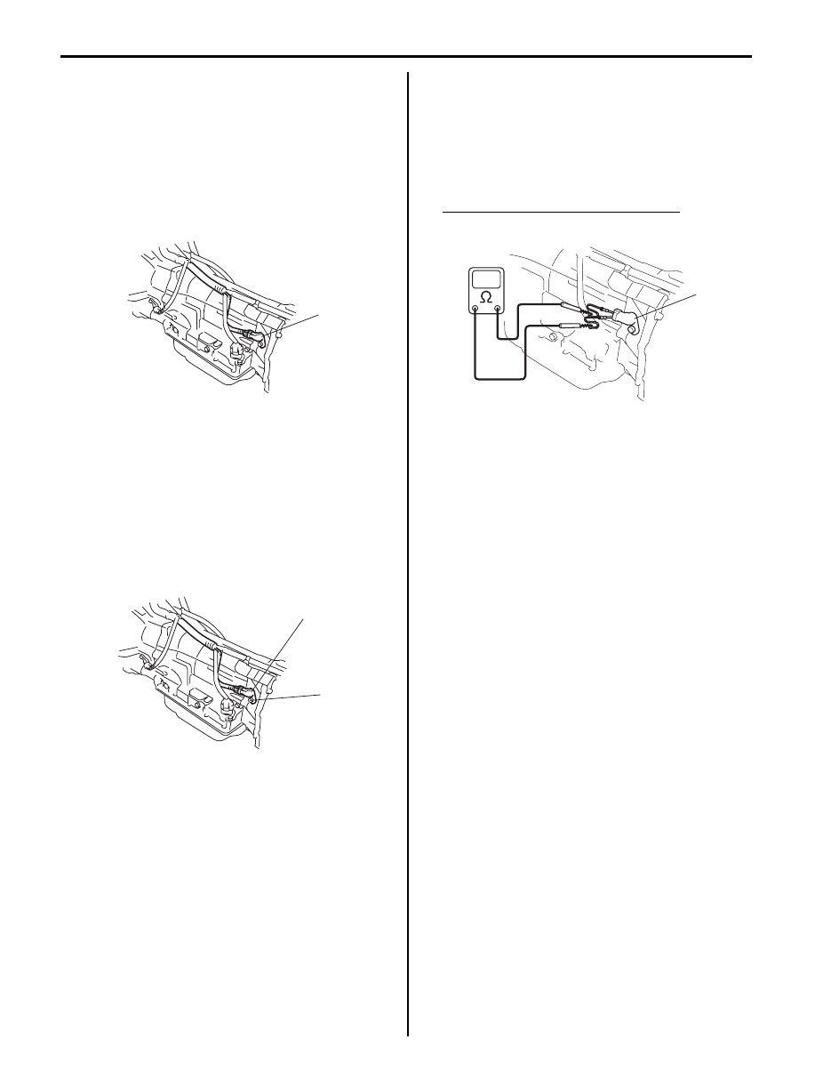
4) Check output shaft speed sensor (1) for resistance 

between terminals of sensor.

Output shaft speed sensor resistance
Standard: 560 – 680 

 (at 20 °C (68 °F))

1

I5JB0A510048-01

1

(a)

I5JB0A510049-01

1

I5JB0A510050-01

Automatic Transmission/Transaxle:  5A-96

Oil Cooler Hose and Pipe Components

S6JB0A5106019

Oil Cooler Hose and Pipes Removal and 
Installation

S6JB0A5106020

Removal

1) Lift up vehicle.
2) Make sure to wash dirt off from around pipe joints.
3) With engine is cool, loosen oil cooler pipe union bolts 

(2) with oil outlet union locked and remove oil cooler 
pipes (1) from oil outlet unions and hoses.

NOTE
To avoid fluid leakage, plug open ends of oil 
outlet unions and hoses right after they are 
disconnected.


I5JB0A510032-03

[A]: View from A side

3. Oil hose No.1

6. Oil pipe No.2

9. Oil pipe No.1 bolt

: 10 N

⋅m (1.0 kgf-m, 7.5 lb-ft)

1. Radiator

4. Oil hose No.4

7. Oil pipe union bolt

10. Oil pipe No.2 bolt

2. Oil hose No.3

5. Oil pipe No.1

8. Oil pipe tube bolt

: 25 N

⋅m (2.5 kgf-m, 18.0lb-ft)

3. Pipe bolt

I5JB0A510153-01

5A-97 Automatic Transmission/Transaxle: 

Installation
When replacing them, be sure to note the followings.
• To replace clamps at the same time
• To insert hose as far as its limit mark
• To clamp hose securely

1) Use new union gaskets and connect oil cooler pipes 

to oil outlet unions.

2) Connect hoses to pipes and clamp them securely.
3) Tighten union bolts to specified torque with oil outlet 

union locked referring to “Oil Cooler Hose and Pipe 
Components”
.

4) Tighten pipe bolt to specified torque referring to “Oil 

Cooler Hose and Pipe Components”.

5) Check A/T fluid level according to procedure 

described in “A/T Fluid Level Check”. Add if 
necessary.

6) Check for fluid leakage after warming up A/T.

Solenoid Valves (Shift Solenoid-A, Shift 
Solenoid-B, TCC Pressure Control Solenoid and 
Pressure Control Solenoid Removal and 
Installation

S6JB0A5106021

Removal

1) Disconnect negative cable at battery.
2) Pull out fluid level gauge and lift up vehicle.
3) Remove drain plug (3) and drain A/T fluid.
4) Install drain plug (3) with new gasket.
5) Remove oil filler tube (2) and A/T oil pan (1).

6) Remove A/T oil strainer (1).

7) Disconnect shift solenoid–A connector (1), shift 

solenoid–B connector (2), TCC pressure control 
solenoid connector (4) and Pressure control solenoid 
connector (3).

8) Remove solenoid valves.

Installation
Remove removal procedure to install solenoid valves, 
noting the following points.
• For details of solenoid valves and their connectors 

installation, refer to “Automatic Transmission Unit 
Assembly”
. Use new O-ring.

• For details of A/T oil pan installation, refer to 

“Automatic Transmission Unit Assembly”.

• Tighten exhaust No.1 pipe bolts & nuts and exhaust 

bracket bolts & nuts.

• Fill A/T fluid and check fluid level according to 

procedure described in “A/T Fluid Change”.

• Check for fluid leakage after warming up A/T.

2

1

3

I5JB0A510051-02

1

I5JB0A510052-01

3

4

1

2

I5JB0A510053-01

Automatic Transmission/Transaxle:  5A-98

Solenoid Valves (Shift Solenoid-A, Shift 
Solenoid-B, TCC Pressure Control Solenoid and 
Pressure Control Solenoid Inspection

S6JB0A5106022

Solenoid Valves (Shift Solenoid–A and Shift 
Solenoid–B)
Resistance check

CAUTION

!


Be very careful as dust etc. does not enter 
when solenoid valves are inspected.


Measure resistance between terminal (2) and solenoid 
valve body. If resistance is out of specification, replace 
solenoid valve.

Shift solenoid–A and Shift solenoid–B resistance
Standard: 11 – 15 

 (at 20 °C (68 °F))

Operation Check
• With solenoid connected to battery (2) as shown in the 

figure, check that solenoid valve is actuated with click 
sound.

• With shift solenoid valve (1) connected to battery (2), 

confirm that shift solenoid valve is open by blowing air 
(50 – 200 kPa, 0.5 – 2.0 kg/cm

2

, 7 – 28.5 psi) into 

solenoid valve as shown in the figure.

• With shift solenoid valve (1) not connected to battery 

(2), confirm that shift solenoid valve is closed by 
blowing air (50 – 200 kPa, 0.5 – 2.0 kg/cm

2

, 7 – 28.5 

psi) into solenoid valve as shown in the figure.

CAUTION

!


Do not insert air gun against strainer 
installed on inlet of solenoid valve too deeply, 
when blowing air into solenoid valve. If not, 
the strainer will be damaged.


Pressure Control Solenoid Valve and TCC Pressure 
Control Solenoid Valve
Resistance check

CAUTION

!


Be very careful as dust etc. does not enter 
when pressure control solenoid valves are 
inspected.


Measure resistance between pressure control solenoid 
valves (Pressure control solenoid and TCC pressure 
control solenoid) (1) terminals. If resistance is out of 
specification, replace valve body assembly.

Pressure control solenoid and TCC pressure control 
solenoid resistance
Standard: 5.0 – 5.6 

 (at 20 °C (68 °F))

1. Shift solenoids

1. Shift solenoids

1

2

I5JB0A510054-01

1

2

I5JB0A510055-01

1

2

1

2

I5JB0A510056-01

1

I5JB0A510057-01


Content   ..  324  325  326  327   ..