Suzuki Grand Vitara JB416 / JB420 / JB419. Manual - part 258
 

  Index      Suzuki     Suzuki Grand Vitara JB416 / JB420 / JB419 - service repair manual 2007 year


Search            


Content   ..  256  257  258  259   ..


Suzuki Grand Vitara JB416 / JB420 / JB419. Manual - part 258


3C-63 Transfer: Motor-Shift Type (Transfer with Shift Actuator)

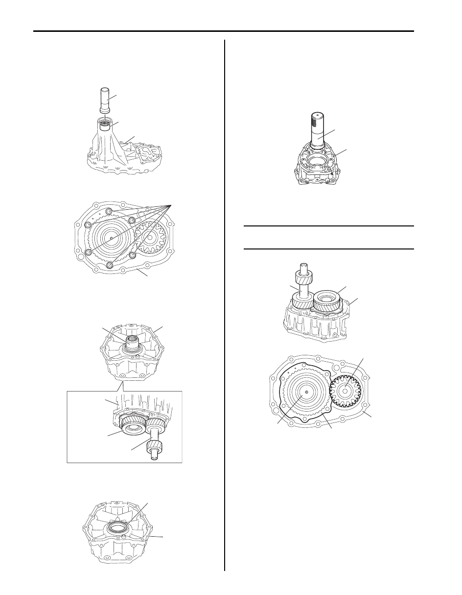
19) Remove needle bearing (1) from rear case (2) using 

special tool, if necessary.

Special tool
(A):  09913–76010

20) Remove input gear plate bolts (1) from front case (2).

21) Remove input gear assembly (1) and counter gear 

assembly (2) from front case (3) using plastic 
hammer.

22) Remove front oil seal No.2 (1) from front case (2) 

using flat end rod or the like, if necessary.

Reassembly

1) Install new front oil seal No.2 to front case (1) using 

special tool, and then apply grease to oil seal lip.

:  Grease 99000–25010 (SUZUKI Super Grease A)

Special tool
(A):  09913–85210

2) Install counter gear assembly (1) to front case (2), 

and then install input gear assembly (3).

NOTE
Install input gear plate (4) so as not to hit 
counter gear assembly.


(A)

1

2

I5JB0A331027-01

1

2

I5JB0A331028-02

3

1

3

1

2

I5JB0A331029-01

1

2

I5JB0A331030-01

(A)

1

I5JB0A331033-01

2

3

1

1

2

4

3

I5JB0A331034-02

Transfer: Motor-Shift Type (Transfer with Shift Actuator) 3C-64

3) Tighten new input gear plate bolts (1) to specified 

torque.

Tightening torque
Input gear plate bolt (a):  23 N·m (2.3 kgf-m, 17.0 
lb-ft)

4) Install needle bearing (1) to rear case (2) using 

special tool as shown in figure.

Distance between case and needle bearing “a”
: 0 – 0.5 mm (0 – 0.008 in.)

Special tool
(A):  09913–76010

5) Install new rear oil seal (1) to rear case (2) using 

special tool as shown in figure, and then apply 
grease to oil seal lip.

“A”:  Grease 99000–25010 (SUZUKI Super 
Grease A)

Distance between case and oil seal “a”
: 3.5 – 4.5 mm (0.138 – 0.177 in.)

Special tool
(A):  09913–70123

6) Install rear output shaft assembly (1) to rear case (2), 

and then install snap ring (3).

7) Install front drive sprocket (1), front output shaft 

assembly (2), drive chain (3) and needle bearing (4) 
into rear case (5).

8) Install front drive sprocket bush (1) into front drive 

sprocket (2).

9) Install differential lock clutch sleeve (1) to rear output 

shaft (2) as shown in figure.

1, (a)

I5JB0A331035-03

(A)

1

2

“a”

I5JB0A331036-02

“a”

(A)

1, “A”

2

1

2

I5JB0A331037-04

1

2

3

I5JB0A331038-01

1

2

3

5

4

I5JB0A331024-01

1

2

I5JB0A331039-01

1

2

I5JB0A331040-01

3C-65 Transfer: Motor-Shift Type (Transfer with Shift Actuator)

10) Install thrust needle bearing (4), front drive shaft (1) 

and needle bearings (2) to rear output shaft (3).

11) Install low gear (3), center differential (4) and 

reduction shift sleeve (1) to rear output shaft (2).

12) Select shim (1) as follows.

a) Install shim, washer (2) and used snap ring (3) 

into rear output shaft (4).

b) Check clearance between shim and washer.
c) If clearance is out of specified value, select shim 

from the following table so that clearance 
become specified value.

Clearance between shim and washer
: 0.1 – 0.3 mm (0.004 – 0.012 in.)

Available shim thickness

13) Remove used snap ring, and then install new snap 

ring (2) and needle bearing (1) to rear output shaft 
(3).

[A]: Rear case side

1

1

2

3

4

I5JB0A331041-02

1

2

4

[A]

4

3

I5JB0A331042-02

0.4 mm (0.016 in.)

1.6 mm (0.063 in.)

0.6 mm (0.024 in.)

1.8 mm (0.071 in.)

0.8 mm (0.031 in.)

2.0 mm (0.079 in.)

1.0 mm (0.039 in.)

2.2 mm (0.087 in.)

1.2 mm (0.047 in.)

2.4 mm (0.098 in.)

1.4 mm (0.055 in.)

1

3

2

4

I5JB0A331043-01

1

2

3

I5JB0A331044-02

Transfer: Motor-Shift Type (Transfer with Shift Actuator) 3C-66

14) Install needle bearings (1) to center case (2) using 

special tools as shown in figure.

Distance between case and needle bearing “a”
: 0 – 0.5 mm (0 – 0.008 in.)

Special tool
(A):  09913–76010
(B):  09925–98210

15) Install oil pipe (1) and knock pin (2) into center case 

(3).

16) Install new front oil seal No.1 (4) into center case 

using special tool as shown in figure, and then apply 
grease to oil seal lip.

Distance between case and oil seal “a”
: 3.5 – 4.5 mm (0.138 – 0.177 in.)

“A”:  Grease 99000–25010 (SUZUKI Super 
Grease A)

Special tool
(A):  09913–70123

17) Clean mating surface of both center case and rear 

case (1), apply sealant to rear case as shown in 
figure by such amount that its section is 1.2 mm 
(0.047 in.) in diameter, mate center case with rear 
case and then tighten bolts (2) to specified torque.

“A”:  Sealant 99000–31260 (SUZUKI Bond 
No.1217G)

Tightening torque
Rear case bolt (a):  23 N·m (2.3 kgf-m, 17.0 lb-ft)

1

2

(B)

(A)

“a”

I5JB0A331045-02

2

1

3

(A)

4, “A”

“a”

I5JB0A331046-03

3. Clamp

“A”

1

3

1

2, (a)

I5JB0A331047-02


Content   ..  256  257  258  259   ..