Suzuki Grand Vitara JB416 / JB420 / JB419. Manual - part 256
 

  Index      Suzuki     Suzuki Grand Vitara JB416 / JB420 / JB419 - service repair manual 2007 year


Search            


Content   ..  254  255  256  257   ..


Suzuki Grand Vitara JB416 / JB420 / JB419. Manual - part 256


3C-55 Transfer: Motor-Shift Type (Transfer with Shift Actuator)

Repair Instructions

Transfer Oil Level Check

S6JB0A3316001

1) Lift up vehicle and check oil leakage.
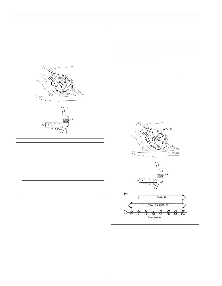
2) Remove oil level/filler plug (1) and check oil level is 

between 0 and 10 mm (0 and 0.394 in.) from the 
lower end of oil level / filler plug hole (2).
If oil level is not in the range, add specified oil up to 
plug hole.

Transfer Oil Change

S6JB0A3316002

1) Before changing oil, be sure to stop engine and lift 

vehicle horizontally.

2) Check leakage.

If leakage exists, correct it.

NOTE
Whenever vehicle is hoisted for any other 
service work than oil change, also be sure to 
check for oil leakage.


3) Remove oil filler plug (2).
4) Remove drain plug (1), and drain oil.
5) Apply sealant to thread of drain plug (1), and tighten 

it to specified torque.

“A”:  Sealant 99000–31260 (SUZUKI Bond 
No.1217G)

Tightening torque
Transfer oil drain plug (a):  23 N·m (2.3 kgf-m, 
17.0 lb-ft)

6) Pour new specified oil up to lower end of oil level / 

filler plug hole (3).

NOTE
It is highly recommended to use API GL-5 
80W-90 gear oil.


Transfer oil specification
: API GL-4 (For SAE classification, refer to 
viscosity chart [A] in figure.)

Transfer oil capacity (Motor-Shift Type)
Reference: 1.5 liters (3.2/2.6 US/lmp. pt)

7) Apply sealant to thread of level / filler plug, and then 

tighten it to specified torque.

“A”:  Sealant 99000–31260 (SUZUKI Bond 
No.1217G)

Tightening torque
Transfer oil level / filler plug (b):  23 N·m (2.3 kgf-
m, 17.0 lb-ft)

“a”. 0 – 10 mm (0 – 0.394 in.)

I5JB0A331001-02

“a”. 0 – 10 mm (0 – 0.394 in.)

I5JB0A331002-03

Transfer: Motor-Shift Type (Transfer with Shift Actuator) 3C-56

Transfer Oil Seal Removal and Installation

S6JB0A3316003

Removal

1) Lift up vehicle and drain transfer oil.
2) Remove front propeller shaft and/or rear propeller 

shaft referring to “Propeller Shaft Removal and 
Installation in Section 3D”.

3) Remove front oil seal No.1 (1) and/or rear oil seal (2) 

using flat end rod or the like.

Installation

1) Install new oil seal using special tool and plastic 

hammer, and then apply grease to oil seal lip.

:  Grease 99000–25010 (SUZUKI Super Grease 
A) 

Special tool
(A):  09913–70123 

2) Install front propeller shaft and/or rear propeller shaft 

referring to “Propeller Shaft Removal and Installation 
in Section 3D”.

3) Fill transfer oil referring to “Transfer Oil Change: 

Motor-Shift Type (Transfer with Shift Actuator)”.

Transfer Switch Removal and Installation

S6JB0A3316004

Removal
Remove HVAC control module referring to “HVAC 
Control Module Removal and Installation in Section 7A”, 
and then remove transfer switch (1) from center cluster 
(2).

Installation
Reverse removal procedure.

2

1

I5JB0A331031-01

(A)

(A)

I5JB0A331032-01

1

2

I5JB0A331003-02

3C-57 Transfer: Motor-Shift Type (Transfer with Shift Actuator)

Transfer Switch Inspection

S6JB0A3316005

Check continuity between following terminals when 
transfer switch (1) operated at each position.

4WD Control Module Removal and Installation

S6JB0A3316006

Removal

1) Disconnect negative (–) cable from battery.
2) If the vehicle is equipped with air bag system, 

disable air bag system. Refer to “Disabling Air Bag 
System in Section 8B”.

3) Disconnect connectors from 4WD control module 

(1).

4) Remove 4WD control module with TCM by removing 

its nuts, and then separate 4WD control module and 
TCM.

Installation
Reverse removal procedure for installation noting the 
following.
• Connect 4WD control module connectors securely.
• If the vehicle is equipped with air bag system, be sure 

to enable air bag system after 4WD control module is 
back in place.
Refer to “Enabling Air Bag System in Section 8B”.

Switch position

Terminal

†

 (2)

1 – 2

N (3)

1 – 2 – 3

4H (4)

1 – 3

4H-lock (5)

1 – 3 – 4

4L-lock (6)

1 – 4

[A]: Transfer switch connector (harness side view)

[A]

6 5 4 3 2 1

6

5

4

3

2

1

I5JB0A331004-04

1

I5JB0A331005-01

Transfer: Motor-Shift Type (Transfer with Shift Actuator) 3C-58

Transfer Assembly Dismounting and 
Remounting

S6JB0A3316007

Dismounting

1) Shift transfer to 4H position operating transfer 

switch.

2) Disconnect negative (–) cable from battery.
3) Remove gear shift control lever (M/T model) 

referring to “Transmission Shift Control Lever 
Removal and Installation: For Petrol Engine Model in 
Section 5B”
 or “Transmission Shift Control Lever 
Removal and Installation: For Diesel Engine Model 
in Section 5B”.

4) Drain transfer oil.
5) Remove front propeller shaft (1) and rear propeller 

shaft (2) referring to “Propeller Shaft Removal and 
Installation in Section 3D”.

6) Remove exhaust center pipe (3) referring to 

“Exhaust Pipe and Muffler Removal and Installation: 
For Petrol Engine Model in Section 1K” 
or “Exhaust 
System Components: For Diesel Engine Model in 
Section 1K”
.

7) Disconnect transfer actuator connector (4), center 

differential lock switch connector (5), 4L/N switch 
connector (6).

8) Support engine rear mounting member (1) with 

transmission jack (2).

9) Remove engine rear mounting bolts (3), and then 

slant the transmission with transfer.

10) Remove gear shift control lever rear case from 

transfer (M/T model).

11) Remove transfer to transmission bolts (upper side), 

and then install engine rear mounting member with 
transmission and transfer.

12) Support transfer assembly (1) with transmission 

jack.

13) Remove transfer to transmission bolts (lower side) 

(2), and then lower transfer assembly.

Remounting
Reverse dismounting procedure for remounting noting 
the following.
• Tighten each bolts and nuts referring to “Transfer 

Assembly Components: Motor-Shift Type (Transfer 
with Shift Actuator)” an
d “Gear Shift Control Lever 
Rear Case Assembly Components: For Petrol Engine 
Model in Section 5B” 
or “Gear Shift Lever Case 
Assembly Components: For Diesel Engine Model in 
Section 5B”.

• Set each clamp for wiring securely.
• Fill transfer oil referring to “Transfer Oil Change: 

Motor-Shift Type (Transfer with Shift Actuator)”.

• Connect battery and check for function.

1

4

3

6

5

2

I5JB0A331006-01

1

2

3

I5JB0A331007-02

1

2

I5JB0A331008-01


Content   ..  254  255  256  257   ..